
check

check

check

check

check

check
<!-- x-tinymce/html -->
Specifying a hydraulic pressure sensor is a six-point decision: confirm the pressure type (gauge, absolute or differential), choose a measuring range so working pressure sits at roughly 60–80% of full scale, verify overload and pressure-spike tolerance, match the process connection and wetted materials to the hydraulic fluid, select the output the controller needs, and qualify the enclosure for the environment. Skip any point and the sensor fails early or reads wrong.
Range is a margin decision, not a maximum. KJT Sensors' selection guidance recommends keeping actual working pressure at 60–80% of the sensor's measuring range, leaving headroom for pressure spikes.
Hydraulics is a shock environment. Pumps, valves and cylinders generate pressure pulsation and water-hammer spikes far above nominal working pressure; overload and shock tolerance decide service life.
The process connection is mechanical and hydraulic at once. Thread form, sealing method and installation position affect both leak-tightness and reading stability.
Wetted materials must match the fluid. The diaphragm and pressure port see the medium directly; material choice is a corrosion decision.
Output follows the control architecture. KJT Sensors' guidance maps 4–20 mA to conventional PLC control, RS485/Modbus to remote or multi-point networks, and HART to smart commissioning.
Pressure type. Hydraulic equipment almost always uses gauge pressure (relative to atmosphere). Absolute pressure applies to vacuum or sealed-reference duties, and differential pressure to two-point comparisons such as filter monitoring. The KJT Sensors YL series publishes all three types.
Range selection. Choose the measuring range so the normal working pressure falls in the upper-middle of the scale — KJT Sensors' published selection guidance recommends 60–80% of the range, reserving the rest for overload. This matters twice over: accuracy is specified as a percentage of full scale (the YL series publishes accuracy classes of ±0.1% FS, ±0.25% FS and ±0.5% FS), so an oversized range throws away reading resolution; and an undersized range lives permanently at its overload limit. The YL series publishes measuring ranges from 0–10 kPa up to 0–40 MPa, covering typical hydraulic working pressures.
Hydraulic systems spike. Valve switching, cylinder bottoming and pump ripple produce transient pressures that can exceed nominal working pressure several times over, and a sensor specified only for nominal pressure fails by fatigue or diaphragm damage. Three checks:
Proof / overload pressure — the maximum pressure the sensor withstands without permanent damage. Confirm the value for the exact model against the system's worst credible spike, including relief-valve setting plus transient overshoot.
Pulsation and water hammer — fast, repeated transients fatigue sensing elements. Snubbers, throttle screws or damping fittings are standard countermeasures where pulsation is severe.
Vibration — mobile and industrial hydraulics vibrate continuously. The YL series documentation describes overload and shock protection designed for pipe pressure shock, hydraulic shock and equipment-vibration scenarios, with vibration-resistant construction for shaken pipework.
Proof-pressure values are model-specific and are not stated in the category-level material reviewed for this article — request the figure for the exact model before finalizing a specification.
Connection. The YL series publishes process connections including M20×1.5, G1/4, NPT1/4, flange and clamp options. Choose by three criteria: the port standard already on the machine, the sealing method appropriate for the pressure class, and the installation position — a sensor mounted at the bottom of a pipe reads differently from one at the top, and trapped air or sediment distorts readings.
Wetted materials. The diaphragm and pressure port contact the hydraulic fluid directly. The YL series publishes SUS316 stainless-steel wetted options, with material selected according to the medium. Standard mineral hydraulic oils are routine; water-glycol, phosphate-ester, biodegradable fluids and aggressive media each require explicit material confirmation. Seal material is part of the same decision.
Environment. The YL series publishes an operating-temperature span of −40 °C to +85 °C with a compensated range of −10 °C to +80 °C, and IP65/IP67 enclosure options — KJT guidance suggests IP65 for dry indoor locations and IP67 for outdoor, wet or dusty installations. Hazardous-area hydraulics are a separate compliance decision requiring explosion-proof configurations and model-level certification.
KJT Sensors' published guidance maps outputs to system architecture, and the YL series publishes 4–20 mA, 0–10 V, RS485, HART and switching-output options:
| Control architecture | Recommended output | Why |
|---|---|---|
| Conventional PLC analog input | 4–20 mA | Current loop tolerates long cable runs and electrical noise; a broken loop reads as zero, which aids fault detection |
| Remote or multi-point network | RS485 / Modbus | One bus serves many sensors with digital values |
| Smart commissioning and diagnostics | HART | Digital configuration and device diagnostics over the analog loop |
| Local alarm or interlock | Switching output | On/off control without an analog input channel |
| Short-run voltage input | 0–10 V | Simple wiring where cable runs are short and noise is low |
The 4–20 mA vs 0–10 V vs RS485 vs IO-Link comparison is a full decision of its own, owned by the interface-selection guide. Output-to-PLC wiring — NPN/PNP switching outputs, common references and input types — is covered in the PLC-integration guide.
This checklist is the original working tool of the article — complete every line before requesting a quotation:
| # | Specification | What to state |
|---|---|---|
| 1 | Pressure type | Gauge / absolute / differential |
| 2 | Working pressure (normal and maximum) | The basis for the 60–80% range rule |
| 3 | Pressure spikes and relief-valve setting | Sizes the proof-pressure requirement |
| 4 | Measuring range | Chosen per items 1–3 (YL series: 0–10 kPa to 0–40 MPa span) |
| 5 | Accuracy class | ±0.1 / ±0.25 / ±0.5 %FS — as a full-scale value, it interacts with range choice |
| 6 | Medium | Fluid type, temperature, viscosity, corrosiveness |
| 7 | Wetted materials and seals | e.g. SUS316 wetted parts; seal material matched to the fluid |
| 8 | Process connection | Thread/flange/clamp standard, sealing method, mounting position |
| 9 | Output signal | 4–20 mA / 0–10 V / RS485 / HART / switching — per control architecture |
| 10 | Environment | Temperature span, vibration, washdown, IP rating (IP65/IP67 options), hazardous-area classification if any |
| 11 | Display and alarms | Local LED display, setpoints, switching thresholds if needed (YL series publishes a 4-digit LED with two configurable switching outputs) |
| 12 | Quantity and destination market | Affects documentation and quotation |
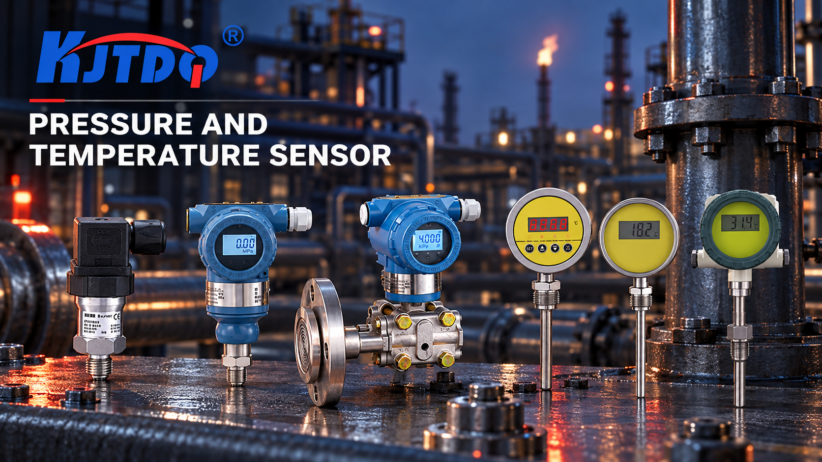
The YL series is KJT Sensors' published pressure line for hydraulic and process duties (all values manufacturer-stated, verified against current documentation 2026-10-10):
Measurement: gauge, absolute and differential types; ranges from 0–10 kPa to 0–40 MPa; accuracy classes ±0.1 / ±0.25 / ±0.5 %FS.
Outputs: 4–20 mA, 0–10 V, RS485, HART and switching outputs; 4-digit LED display with two configurable switching outputs for local alarms and interlock.
Construction: piezoresistive sensing with isolated oil-filled diaphragm; SUS316 wetted options; temperature compensation; overload and shock protection; IP65/IP67 options; operating span −40 °C to +85 °C.
Connections: M20×1.5, G1/4, NPT1/4, flange and clamp options.
Sibling lines: precision digital pressure sensors, intelligent pressure-control sensors and pressure transducers are listed on the pressure and temperature category page; temperature transmitters and infrared thermometers complete the process-measurement range.
For the broader application-data set to send with any sensor inquiry, see the application-information checklist.
Published YL-series values are manufacturer-stated and model-scoped; the proof-pressure rating, long-term drift and exact temperature error for a specific model must be confirmed on its data sheet before specification.
Very fast pressure transients (hydraulic-fracture test stands, water-hammer research) require high-bandwidth dynamic pressure sensors outside the scope of general transmitters.
Sanitary and hazardous-area hydraulics carry additional compliance requirements; explosion-proof selection requires model-level certificates and qualified review.
If a correctly installed sensor drifts in service, that is a troubleshooting case — see the pressure-drift guide.
How much pressure-range margin is appropriate? KJT Sensors' published guidance recommends keeping actual working pressure at 60–80% of the sensor's measuring range. This preserves resolution (accuracy is specified as % of full scale) while leaving headroom for spikes. Then separately confirm the proof-pressure rating of the exact model against the system's worst credible transient, including relief-valve overshoot.
Which output should a hydraulic pressure sensor use? Match the control architecture: 4–20 mA for conventional PLC analog inputs, RS485/Modbus for remote multi-point networks, HART for smart commissioning, switching outputs for local alarms, 0–10 V for short low-noise runs. The full interface comparison is covered in the interface-selection guide.
What causes pressure readings to drift after installation? Common causes include installation vibration, medium temperature beyond the compensated range, wiring and grounding problems, and zero shift — the pressure-drift troubleshooting guide works through the diagnosis. KJT's FAQ guidance similarly starts with vibration, medium temperature, cable and grounding checks, then zero calibration.
Do I need a snubber on a hydraulic pressure sensor? Where the system produces fast, repeated pulsation or water hammer — piston pumps without accumulators, fast-switching valves — a snubber or damping fitting protects the sensing element and steadies the reading. Steady systems with slow dynamics usually do not need one. Confirm the transient profile of your circuit before deciding.
Which process connection should I choose? Match the port standard already designed into the machine (the YL series publishes M20×1.5, G1/4, NPT1/4, flange and clamp options), verify the sealing method suits the pressure class, and choose a mounting position that avoids trapped air and sediment. Adapters are possible but add leak paths and dead volume.
What information should I send for a hydraulic pressure-sensor quotation? Pressure type, working and maximum pressure, spike profile, medium, wetted-material requirements, process connection, output signal, environment (temperature, vibration, IP, hazardous area), display/alarm needs and quantity — the twelve checklist items above.
A hydraulic pressure sensor specification is six linked decisions — pressure type, range margin, spike tolerance, connection and wetted materials, output, and environment — and the range question is really a margin question: working pressure at 60–80% of scale, with proof pressure verified against real transients. Complete the twelve-point checklist and the correct model almost selects itself.
Ready to specify a hydraulic pressure sensor? Send KJT Sensors your pressure-system details from the checklist — the application team will recommend a YL-series configuration. Browse the pressure and temperature range or start from the product center.
| # | Source | Type | Used for |
|---|---|---|---|
| 1 | KJT Sensors Pressure and Temperature Category Knowledge Base — YL-series product data (internal, 2026) | KJT Sensors internal documentation | YL series: gauge/absolute/differential; 0–10 kPa to 0–40 MPa; ±0.1/0.25/0.5 %FS; 4–20 mA / 0–10 V / RS485 / HART / switching; −40~+85 °C operating, −10~+80 °C compensated; IP65/IP67; SUS316 wetted; M20×1.5 / G1/4 / NPT1/4 / flange / clamp; 60–80% range guidance; output-selection guidance; overload/shock protection (all manufacturer-stated) |
| 2 | KJT Sensors pressure and temperature category page — https://www.kjt-sensors.com/list-yl_wdcgq.html (verified 2026-10-10) | KJT Sensors first-party | Subcategory structure: precision digital pressure, digital temperature, intelligent pressure control, temperature transfer, pressure transducers |
| 3 | KJT Sensors product center — https://www.kjt-sensors.com/list-product.html (verified 2026-10-10) | KJT Sensors first-party | Portfolio navigation |