
check
check

check

check
check
check
check
check

check

check
Select an inductive proximity sensor in this order: confirm that the target is metal; identify the metal and target size; choose flush or non-flush construction from the surrounding metal; verify that the exact model's assured operating distance covers the worst-case gap; then check switching frequency, output, housing, connector and environment. Do not design from nominal sensing distance alone, and do not apply a generic non-ferrous correction factor when the model data sheet provides its own value.
Inductive sensors detect conductive metal targets; plastic, glass, wood and most liquids require another principle.
Nominal sensing distance is not the same as guaranteed working distance under voltage and temperature variation.
Flush models tolerate surrounding metal at the mounting face; non-flush models require the manufacturer's specified free zone.
Range on stainless steel, aluminum, brass or copper depends on the exact sensor design and target geometry.
Fast targets require a switching-frequency check based on event frequency and target/gap dimensions.
Final selection requires the exact model data sheet and, for marginal targets, a representative sample test.
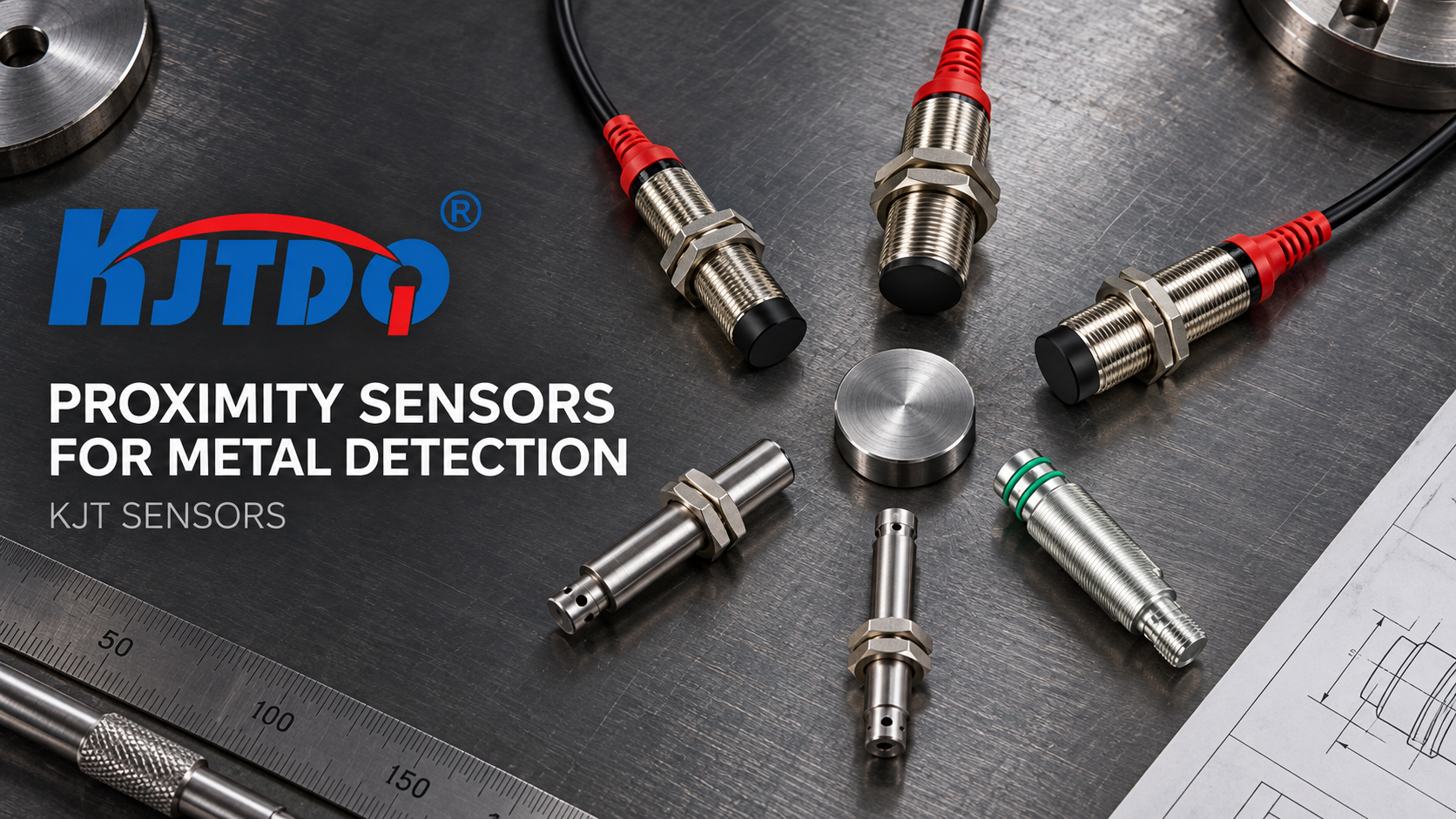
An inductive proximity sensor detects metal by generating an electromagnetic field at the sensing face and monitoring how a conductive target changes the oscillator. It is commonly used for non-contact position confirmation, part presence, counting and end-of-travel sensing.
This “metal only” behavior can be useful. An inductive sensor can detect a steel flag while ignoring a plastic guard or many non-metallic contaminants. It is not suitable when the required target is cardboard, glass, wood or a non-conductive plastic part.
The current IEC 60947-5-2:2019 standard covers inductive and other proximity switches and defines relevant construction, performance and test requirements.
Use the exact model's assured or guaranteed operating distance, not only the nominal sensing distance shown in a category table. IEC terminology distinguishes nominal, effective, usable and assured operating distances. Voltage, temperature, production tolerance, target size, target material and approach geometry can all reduce the practical switching distance.
| Term | Engineering meaning | Design use |
|---|---|---|
| Nominal sensing distance (Sn) | A type-designation or reference value under defined standard conditions | Useful for comparing models, not sufficient for final tolerance design |
| Effective/usable operating distance | Values that account for specified device and operating-condition tolerances | Check the model documentation and test conditions |
| Assured operating distance (Sa) | The zone in which correct operation is assured under the stated standard conditions | Use as the upper boundary for worst-case gap design |
Do not replace the model's published value with a simplified multiplier unless the data sheet or approved engineering rule explicitly supports it. Leave additional mechanical margin for bracket tolerance, target runout, thermal movement and wear.
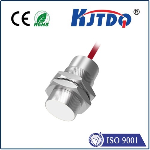
A flush (shielded) inductive sensor can be embedded in surrounding metal up to the permitted mounting plane. A non-flush (unshielded) sensor projects more of its field sideways and therefore needs a metal-free zone around the sensing face.
| Installation condition | Preferred construction | Reason |
|---|---|---|
| Sensor threaded into a steel plate | Flush | Surrounding metal is part of the intended mounting geometry |
| Restricted slot with nearby metal | Flush | Concentrated field reduces interaction with adjacent metal |
| Open non-metallic bracket and more range is needed | Non-flush may fit | The required free zone may be available |
| Dense sensor spacing | Usually flush | Easier to control adjacent-metal and mutual-interference effects |
| Existing unknown installation | Verify before replacement | A visually similar sensor may have different mounting requirements |
Installing a non-flush model inside surrounding metal can reduce range, shift the switching point or cause an unintended active state. The required axial and radial clearance is model-specific; use the drawing and installation instructions rather than a universal multiple of Sn.
Steel is normally the reference target, so the mechanical gap and mounting environment become the first decisions.
Use this sequence:
measure the minimum and maximum target gap, including runout and bracket tolerance;
determine whether surrounding metal requires a flush model;
select a housing that fits the space and provides an assured distance beyond the maximum gap;
confirm that adjacent metal and nearby sensors meet the model's clearance rules;
calculate the shortest time the target occupies the sensing zone;
verify output, connector and environment.
A larger flush sensor may be the correct solution when a smaller non-flush sensor offers more nominal range but cannot obtain the required metal-free mounting zone.
Non-ferrous targets often produce less sensing distance than the mild-steel reference target, but the reduction is not one universal table. Stainless-steel composition, aluminum, brass and copper can produce different correction factors, and “factor 1” models are designed to reduce material-dependent variation.
| Target condition | What to verify |
|---|---|
| Mild steel | Standard target size, thickness and assured distance |
| Stainless steel | Model-specific correction factor and alloy effect |
| Aluminum, brass or copper | Model-specific reduction factor or factor-1 capability |
| Thin sheet or foil | Minimum target thickness and sample-test result |
| Small target | Target-size correction relative to the standard target |
| Angled or curved target | Approach direction and switching-point variation |
If the data sheet does not state the material or geometry needed for the application, treat it as an evidence gap and test a sample. Do not attribute generic correction-factor numbers to IEC 60947-5-2 unless the referenced clause actually defines them for that model type.
Housing size affects available coil area, mounting strength and achievable sensing distance, but there is no universal range for every M8, M12, M18 or M30 sensor. Standard, extended-range, compact and factor-1 models can differ substantially within one diameter.
Choose housing size from:
available mechanical envelope and thread;
required assured distance;
target size and material;
flush/non-flush mounting;
connector or cable clearance;
exposure to impact, chips, coolant or washdown.
Where a small housing cannot provide adequate guaranteed distance, redesign the target or bracket, choose an extended-range model with suitable mounting rules, or move to another sensing point.
The sensor must switch reliably for the fastest target event, and the controller must be able to capture it. For a gear or evenly spaced targets:
event frequency (Hz) = number of targets per revolution × rotational speed (rpm) ÷ 60
Select a sensor with documented switching frequency above the calculated event frequency, with engineering margin for target size, gap and speed variation. Also confirm the PLC input filter and scan/capture method. A sensor rated for the pulse rate can still produce missed counts if the input module filters out the pulse.
Confirm the target is conductive metal.
Record material, size, thickness and approach direction.
Measure the worst-case mechanical gap.
Choose flush or non-flush from surrounding metal and clearance.
Verify assured operating distance and target correction from the exact data sheet.
Check switching frequency and controller capture.
Match supply, output, logic, connector and pinout.
Verify temperature, ingress, chemicals, impact and required documents; then sample-test marginal applications.

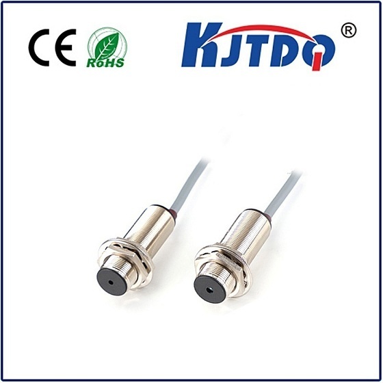
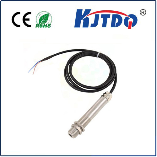
KJT Sensors lists standard and application-specific inductive proximity sensor variants. The inductive proximity sensor category is the correct starting point; the final choice must come from the exact model documentation.
| Application need | Variant to investigate | Evidence required |
|---|---|---|
| General metal presence | Standard inductive proximity sensor | Sn/Sa, target, mounting and output |
| More range in the same general format | Extended-range model | Guaranteed range and clearance requirements |
| Hot, cold or wet environment | Environmental variant | Exact temperature, IP and material documentation |
| Abrasion or metal impact | Full-metal construction | Face material and documented mechanical/environmental limits |
| Analog position indication | Analog-output model | Measuring behavior, output scaling and accuracy terms |
| Hazardous area | Certified model specifically approved for the intended location | Exact certificate, model and application review |
KJT Sensors also provides model-selection and application-review support through its service page.
This is a calculation example, not a customer case or product-performance claim. A steel target flag passes a sensor mounted in a metal machine frame. The target gap varies because of bracket tolerance and slide movement.
The correct process is to:
measure the full gap tolerance rather than only its nominal value;
select a flush model because the sensor is embedded in metal;
compare the maximum gap with the exact model's assured distance;
confirm that the target flag meets the model's reference-target assumptions or apply documented corrections;
verify target dwell time and switching frequency;
test the chosen model across the full mechanical tolerance before design release.
No specific KJT Sensors model should be named until its data sheet and the application dimensions have been checked.
An inductive proximity sensor is a common choice. Use a metal target flag, select flush/non-flush construction from the bracket geometry and keep the worst-case gap within the exact model's assured operating distance.
First verify whether a non-flush model is surrounded by metal or whether metal chips have accumulated near the face. Also check the bracket position, target geometry, wiring and model-specific mounting clearance before replacing the sensor.
Possibly, but thin non-ferrous targets can produce much less response than the standard steel target. Use the model's minimum target requirements and test the actual foil, support structure and gap.
Calculate teeth × rpm ÷ 60, then select a switching frequency and controller input with adequate margin. Confirm that tooth width and gap are large enough for the sensor to resolve separate events.
Inductive proximity selection is a controlled geometry problem: target metal, target size, worst-case gap, surrounding metal and event speed. Use the exact model's assured distance and mounting rules, not a nominal range or generic correction table. KJT Sensors can shortlist models after receiving the target, gap, mounting drawing, speed, environment and PLC interface.
Need a model recommendation? Send the application details through KJT Sensors service and support.
KJT Sensors inductive proximity sensor category, reviewed 2026-09-29.
KJT Sensors flush/non-flush application note, reviewed 2026-09-29.
KJT Sensors service and support, reviewed 2026-09-29.
IEC 60947-5-2:2019 — Proximity switches.
Content Notice: This draft provides general engineering guidance. Operating distance, material effects, mounting clearances, switching frequency and environmental limits must be verified from the exact model data sheet. Hazardous-area applications require qualified review and model-specific certification. A named technical reviewer must approve this article before publication.