

check

check

check

check
check
check
check
check

check

check
Choose through-beam when both sides of the line are accessible and maximum operating margin is the priority. Choose polarized retro-reflective when only one side can be wired and the target is opaque or glossy. Use a dedicated clear-object model—not an ordinary retro-reflective sensor—for transparent bottles or film. Choose diffuse sensing for simple, controlled targets, and background suppression when equipment behind the target could be mistaken for the target. ToF is useful when the decision must be based on distance, but every model still needs testing on the real material and surface.
Through-beam normally provides the strongest signal margin but requires an emitter and receiver on opposite sides.
Retro-reflective sensing uses one wired device plus a reflector; polarization helps reject direct reflections from shiny targets.
Transparent objects require a model designed and adjusted for the small signal change they produce.
Background suppression separates target and background by geometry or distance rather than brightness alone.
Response time must be checked against both the shortest target and the smallest gap at maximum line speed.
The final choice should be validated with worst-case products, backgrounds and contamination.
The modes differ in where the receiver is located and what optical change produces the switching decision.
| Mode | Optical arrangement | Main strength | Main limitation | Typical packaging use |
|---|---|---|---|---|
| Through-beam | Separate emitter and receiver | High operating margin and clear beam-break logic | Both sides need hardware and alignment | Carton counting, part detection and long spans |
| Retro-reflective | Sensor and receiver in one housing; reflector opposite | One wired device and a defined return path | Reflector condition and shiny targets require attention | Conveyor presence and counting |
| Polarized retro-reflective | Retro-reflective with polarization filtering | Better rejection of mirror-like direct reflections | Not automatically a clear-object sensor | Glossy cartons, foil and wrapped loads |
| Clear-object retro-reflective | High-sensitivity/low-hysteresis design for small attenuation | Designed for glass, PET and transparent film | Setup and contamination margin are critical | Clear bottles, trays and film |
| Diffuse | Target returns light directly | Simplest one-sided installation | Color, surface and background affect range | Stable opaque targets at short range |
| Background suppression (BGS) | Receiver evaluates return geometry/distance | Rejects a background beyond the set point | Black/white range difference and alignment still matter | Mixed-color cartons against rails or belts |
| ToF photoelectric | Measures light travel time | Distance-based decision and longer-range options | Very dark, transparent or specular targets can still reduce margin | Gap, height and position-dependent detection |
The IEC 60947-5-2:2019 standard covers photoelectric proximity switches and includes updated requirements for background-suppression devices. Use the exact data sheet for range, response, output and environmental values.
On a narrow packaging line, choose from access and target behavior rather than conveyor width alone.
| Decision factor | Through-beam | Retro-reflective |
|---|---|---|
| Wired devices | Emitter and receiver | Sensor only; passive reflector opposite |
| Signal margin | Generally highest | Usually lower than through-beam |
| Alignment | Two powered devices must share one optical path | Sensor must align with the specified reflector |
| Glossy opaque target | Reliable beam interruption | Use a polarized model to reduce direct-reflection errors |
| Transparent target | Possible only with suitable sensitivity and testing | Use a dedicated clear-object model |
| Maintenance | Two optical faces | Sensor face plus reflector |
Conditional conclusion: use through-beam when the far side is accessible and reliability under contamination is the priority. Use polarized retro-reflective when reducing wiring or preserving one-sided service access matters more. For clear targets, qualify a dedicated transparent-object solution rather than assuming either standard mode will work.
Start with through-beam or retro-reflective beam interruption for consistent opaque products, then calculate the shortest valid signal duration.
Use both calculations:
blocked time = shortest target length in travel direction ÷ maximum line speed
clear time = smallest gap between targets ÷ maximum line speed
The complete signal chain—sensor, input filter and control logic—must resolve the shorter of those two times with adequate design margin. A fast sensor cannot compensate for an input module configured with a longer delay.
Also verify:
target position variation across the conveyor;
lens and reflector contamination;
mechanical vibration and alignment;
output type and controller input;
required count accuracy and test duration.
Use a dedicated clear-object retro-reflective sensor, a suitably configured through-beam system, or a model whose ToF documentation specifically covers the target. Transparent objects may change the optical signal only slightly through refraction, reflection and attenuation, so an ordinary diffuse sensor or standard retro-reflective unit can miss them.
For a clear-object trial, include:
the clearest and thickest permitted walls;
empty and filled containers;
labels, seams, ribs and caps;
condensation or water droplets;
nested or overlapping film;
the full lateral and angular position range.
KJT Sensors publishes a transparent-material detection application note and lists ToF/photoelectric options in its product range. Treat family descriptions as a shortlist only; verify the exact model with production samples.
Use BGS when a target must be detected in front of a fixed or changing background and one-sided mounting is required. BGS uses the geometry of the returned light to distinguish a foreground target from a background beyond the set distance.
Set and test the cutoff using:
the nearest and farthest valid target positions;
the darkest and brightest target surfaces;
the most reflective permitted background;
conveyor or bracket movement;
the model's documented black/white range behavior.
BGS reduces background sensitivity; it does not make target material irrelevant. If target depth varies widely, a ToF sensor or cross-conveyor beam may provide a more stable decision.
Fiber-optic sensing separates the small optical head from the electronics; ToF adds a distance measurement or distance-based switch point.
Choose fiber optics where mounting space is extremely limited, the sensing point is hot, or a small spot is required.
Choose ToF where distance, height or gap determines the decision and ordinary intensity-based sensing is unstable.
Keep the amplifier or controller in a location compatible with its temperature and environmental rating.
Verify the fiber bend radius, response time and optical head arrangement.
Verify ToF behavior on the actual color, transparency, angle and ambient light.
Define the target: material, color, transparency, gloss, shape and smallest dimension.
Map the geometry: available mounting sides, range, background and target position variation.
Choose the mode: through-beam, polarized retro-reflective, clear-object, diffuse, BGS, fiber or ToF.
Calculate event time: shortest target and smallest gap at maximum speed.
Check optical margin: dust, washdown, ambient light and reflector condition.
Match the interface: supply, PNP/NPN, NO/NC, connector and input filter.
Check environmental limits: temperature, IP rating, cleaning chemicals and vibration.
Run an acceptance test: worst target, worst background, worst speed and defined pass/fail criteria.

| Packaging task | Starting category | Required model-level verification |
|---|---|---|
| Opaque carton or bottle counting | Photoelectric sensors | Mode, range, response time and output |
| Clear bottle or film detection | ToF laser photoelectric sensors and clear-object options | Target-specific performance and setup |
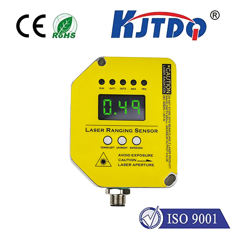
| Distance, gap or position | Laser distance sensors | Measuring range, repeatability, update rate and interface |
| Custom mounting or interface | KJT Sensors service and support | Drawing, model code, documents and sample plan |
This is a design exercise, not a customer case or performance claim. A line must count clear PET bottles, but the original diffuse sensor produces misses and occasional reflections from curved bottle shoulders.
The engineering path is:
classify the target as transparent and glossy;
reject ordinary diffuse sensing as the default solution;
compare dedicated clear-object retro-reflective, suitable through-beam and documented ToF options;
calculate blocked and clear time from the actual bottle and gap dimensions;
confirm PLC input and connector requirements;
test empty/filled, wet/dry, labeled/unlabeled and position extremes;
approve a model only after it meets the written count and false-trigger criteria.
No detection-rate result should be published unless it comes from an identified model, controlled method and retained test record.
Usually these should be separate tasks. Presence detection uses beam interruption or distance; registration requires a small spot, fast response and contrast-specific behavior. Select and validate each function independently.
The film can return a strong direct reflection. A polarized retro-reflective model and suitable mounting geometry reduce that error. Test the most reflective film and seam orientation used in production.
Calculate the shortest blocked and clear times, then include the input filter and controller logic. Select a documented response time that provides adequate design margin for the complete system.
No. ToF reduces dependence on return intensity, but signal strength and measurement quality can still change with dark, transparent, highly reflective or angled targets. Verify the exact model on samples.
Photoelectric reliability is determined first by sensing mode. Through-beam maximizes operating margin, polarized retro-reflective simplifies one-sided wiring for opaque or glossy targets, dedicated clear-object sensing handles transparent products, and BGS separates foreground targets from backgrounds. Calculate timing, verify the interface and validate the exact KJT Sensors model on worst-case production samples.
Need a model shortlist? Send the target samples, line speed, mounting sketch, background and PLC interface through KJT Sensors service and support.
KJT Sensors photoelectric sensor category, reviewed 2026-09-29.
KJT Sensors transparent-material detection note, reviewed 2026-09-29.
KJT Sensors service and support, reviewed 2026-09-29.
IEC 60947-5-2:2019 — Proximity switches.
Content Notice: This draft provides general engineering guidance. Category descriptions do not establish model-level performance. Verify range, response, output, environmental limits and target behavior using the exact data sheet and a representative application test. A named technical reviewer must approve this article before publication.