

check

check

check

check

check

check

check
check
check
check
In steel structure fabrication workshops, overhead cranes frequently lift and transport steel plates, structural profiles, and semi-finished products. When two cranes operate within the same bay, operators must simultaneously monitor the suspended load, unloading positions, and the adjacent crane. Under such conditions, judging approach distances is easily compromised by obstructed lines of sight and rapid operational paces.
Tailored for this scenario, the KJT Smart Laser Overhead Crane Anti-Collision System integrates real-time distance monitoring, voice alerts, and deceleration/stop interlocking to add an active layer of proximity risk prevention for dual cranes sharing a single bay.

This solution utilizes the Smart Laser Overhead Crane Anti-Collision System (Touchscreen Edition), configured on the principle of independent detection and separate integration into each crane's electrical control system.
| System Component | Role in the Solution |
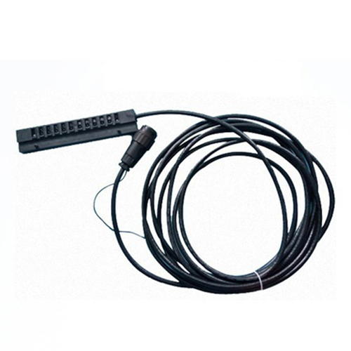
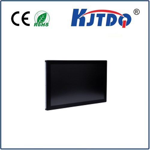
| Anti-Collision Control Host | Displays real-time distance and operational status, configures deceleration and stop thresholds, and provides voice alerts along with relay outputs. |
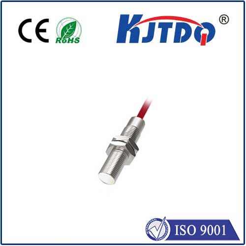
| Laser Distance Sensor Unit | Mounted on the side of each crane facing the adjacent crane to continuously monitor the approach distance. |
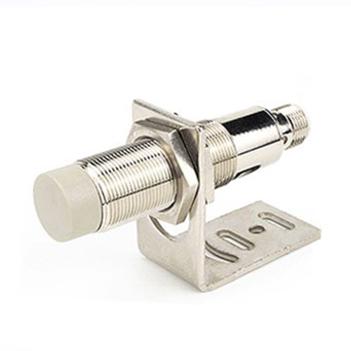
| Matching Reflector Plate | Configured based on model selection and site conditions; fixed to the corresponding position on the opposing crane as the measurement target. |
*Note: Exact configurations are subject to on-site confirmation.
During installation, both the distance sensor unit and the target reflector must be securely mounted with an unobstructed optical path, completely clear of interference from lifting tackle and materials. Additionally, the measured distance must be calibrated against the actual physical clearance between the crane structures.
Based on actual crane operating conditions, two-stage trigger thresholds are established for deceleration and stopping:
Safe Distance: Continuously displays real-time separation distance, allowing operators to clearly track the adjacent crane's position.
Entering Deceleration Zone: Triggers voice alerts and sends a deceleration signal to the crane's electrical control system.
Entering Stop Zone: Outputs a stop signal, which is executed by the integrated crane control and braking system.
The system provides detection and control signals, while actual deceleration and stopping are executed in coordination with the crane's existing electrical control system. When both cranes are capable of movement, both must be integrated into the interlocking system rather than restricting only one. By converting proximity into clear alerts and automated control triggers, this approach minimizes reliance on manual visual estimation.
Before deployment, three critical site conditions must be verified:
| Verification Item | Key On-Site Requirements |
| Operation & Braking | Approach speeds of both cranes, load conditions, control response times, and actual braking distances. |
| Installation & Environment | Mounting locations, target alignment, potential optical path obstructions, and ambient dust/contamination levels. |
| Electrical Control & Fail-Safe Logic | Deceleration/stop control interfaces, as well as fail-safe handling logic during power loss, wire disconnection, or sensor anomalies. |
Deceleration and stop thresholds must include adequate safety margins, with system design, commissioning, and final acceptance completed by the equipment manufacturer or system integrator. All original limit switches, emergency stops, and buffer protections must remain intact, as this system supplements—rather than replaces—the crane's existing safety mechanisms.
Provide details on your crane quantity, runway layout, operating conditions, and electrical control interfaces, and KJT will assist in matching the optimal sensing configuration and anti-collision interlocking solution.