
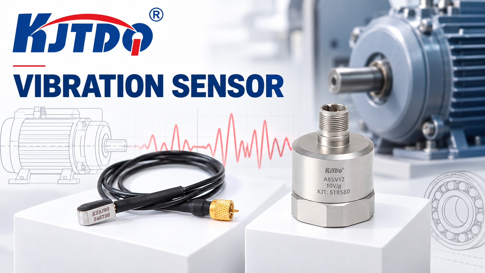
check
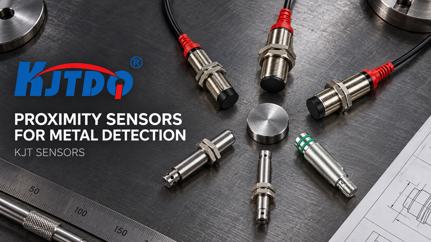
check

check

check
check
check
check
check

check

check
Use vibration velocity for broad machine-condition trending, acceleration or acceleration spectra for higher-frequency bearing and gear information, displacement for low-frequency motion or shaft-relative measurement where the machine design calls for it, and a separate rotational-speed signal for stopped-shaft, underspeed, overspeed or slip monitoring. Select evaluation limits from the applicable machine-specific standard, OEM guidance and a qualified reliability review; do not apply one generic ISO severity table to every motor, pump, fan, gearbox or turbine.
Velocity, acceleration and displacement describe different parts of machine behavior and are not interchangeable.
Overall vibration trending can reveal change; a spectrum or waveform is normally required to diagnose the cause.
Rotational speed is a separate measurement and should be correlated with vibration and operating load.
ISO 20816-1 provides general measurement and evaluation guidance; machine-specific parts and OEM limits govern many applications.
Baselines must record machine state, sensor location, direction, mounting and signal settings.
Safety or regulatory trip functions require an appropriately designed and validated protection system.
Choose the quantity from the machine, fault frequencies and monitoring objective.
| Quantity | Common unit | Best used for | Important limitation |
|---|---|---|---|
| Displacement | µm peak-to-peak or other specified form | Low-frequency motion and shaft-relative measurement on machines designed for proximity probes | Housing displacement and shaft-relative displacement are different measurements |
| Velocity | mm/s RMS over a defined band | Broad severity and trend monitoring on many rotating machines | Overall value does not identify the fault by itself |
| Acceleration | m/s² or g, peak/RMS as specified | Higher-frequency bearing, gear and impact information | Results depend strongly on bandwidth, mounting and signal processing |
| Envelope/demodulated acceleration | Defined engineering units | Early rolling-element bearing signatures | Settings and bearing frequencies must be documented |
Always record whether a value is RMS, peak or peak-to-peak and the frequency band over which it was calculated. Two values with different bands or amplitude conventions are not directly comparable.
ISO 20816-1:2016 establishes general conditions and procedures for measuring and evaluating vibration on complete machines. It does not justify using one universal set of alarm values for every machine.
The correct evaluation path is:
identify the machine type, power, speed, support and bearing arrangement;
select the applicable machine-specific part of the ISO 20816 series, if one exists;
use the specified measurement location, quantity, frequency band and operating condition;
compare with OEM limits, commissioning data and site risk policy;
establish alert and action levels through qualified review;
preserve the machine's baseline and investigate meaningful change.
Legacy ISO 10816 class tables are still reproduced widely online, but they should not be presented as current universal pass/fail limits. A value can be acceptable under one machine-specific standard and inappropriate under another.
A baseline shows how the specific machine behaves when its condition and operating state are known. Trend comparison is useful only when the measurement is repeatable.
Record:
machine speed, load, process state and temperature;
sensor location and measurement direction;
mounting method and surface condition;
quantity, amplitude convention and frequency band;
acquisition or transmitter settings;
maintenance state and date.
A percentage-change alarm should not be copied from a generic article. Set change criteria from measurement uncertainty, normal operating variability, failure consequence and the applicable standard or analyst recommendation.
Overall vibration is a screening and trending value. It can show that machine behavior has changed, but it usually cannot prove the root cause. Imbalance, misalignment, looseness, resonance, hydraulic/aerodynamic effects and bearing damage can all influence the reading.
Use overall velocity when the goal is to monitor broad machine condition through a PLC or monitoring system. Escalate to waveform, spectrum, phase, envelope or process analysis when:
the trend rises persistently;
alert or action criteria are crossed;
the machine produces a new sound or temperature change;
maintenance decisions require fault identification;
the vibration changes with speed or load in an unexpected way.
Avoid one-line diagnoses such as “1× always means imbalance” or “2× always means misalignment.” Frequency patterns are clues that must be interpreted with direction, phase, harmonics, machine structure and operating condition.
Use acceleration and frequency analysis when higher-frequency content or fault identity matters. Rolling-element bearing defects, gear mesh, impacts and lubrication problems may appear in acceleration or demodulated data before an overall velocity trend becomes decisive.
The analysis requires more than a sensor label. Verify:
sensor sensitivity and frequency response;
mounting stiffness and surface preparation;
sampling rate and anti-alias filtering;
frequency span, resolution and windowing;
bearing geometry and shaft speed;
consistent load and operating state.
A permanently installed 4–20 mA vibration transmitter may be appropriate for simple overall trending, but it normally does not provide the raw waveform needed for detailed spectral diagnosis. Confirm what the output represents for the exact model.
Displacement is useful for low-frequency motion and for shaft-relative measurements on machines designed for eddy-current proximity probes. A casing-mounted displacement measurement is not the same as a probe measuring the shaft relative to the bearing housing.
For shaft-relative monitoring, verify probe target material, probe/extension cable/driver matching, calibrated range, mounting, runout and the machine standard. Axial position and radial shaft vibration also serve different purposes and require different probe arrangements.
Use a dedicated speed sensor or a suitable proximity pickup aimed at a defined target such as a gear tooth, key, bolt or pulse wheel. The controller converts pulse frequency into rotational speed.
rotational speed (rpm) = pulse frequency (Hz) × 60 ÷ pulses per revolution
Check:
target material, width and spacing;
sensor air gap and runout allowance;
maximum pulse frequency;
minimum detectable speed and zero-speed behavior;
controller time window and input filter;
required delay before declaring stopped, underspeed or overspeed.
Passive variable-reluctance pickups can produce weaker output at low speed; active Hall or inductive arrangements may be more suitable where near-zero operation must be resolved. The exact low-speed behavior must come from the model data sheet and test setup.
For belt-slip monitoring, compare the relevant pulley or shaft speeds using a defined ratio and time delay. If the signal performs a safety function, use a protection architecture appropriate to the risk assessment; a standard monitoring sensor is not automatically safety-rated.
Use wired transmitters where continuous availability, local power and integration with an existing PLC or monitoring rack justify cabling. Use wireless nodes where cabling is impractical and the required update interval, battery plan and radio path support condition monitoring.
| Decision | Wired transmitter | Wireless node |
|---|---|---|
| Power | Continuous local supply | Battery or local power |
| Data timing | Continuous or frequent | Scheduled/event-based, model-dependent |
| Installation | Cable and I/O required | Radio survey, gateway and battery plan required |
| Best fit | Critical or accessible assets | Distributed retrofit monitoring |
| Main risk | Cable/grounding/integration | Coverage, packet delivery, battery and cybersecurity |
Neither architecture should be selected from asset count alone. Base the decision on criticality, data rate, response need, maintenance resources and integration requirements.

KJT Sensors lists vibration, speed, displacement and wireless monitoring product families. Match the category to the measurement task, then verify the exact model.
| Monitoring task | Starting category | Model-level evidence required |
|---|---|---|
| Overall vibration trending | Vibration sensors and transmitters | Measurand, band, amplitude convention, range and output |
| Speed, stopped-shaft or slip input | Speed sensors | Target, gap, speed range, switching frequency and output |
| Shaft-relative displacement | KJT Sensors product center | Probe system, target material, calibrated range and installation |
| Distributed retrofit monitoring | KJT Sensors product center | Radio, interval, battery, gateway and integration |
| Application review | KJT Sensors service and support | Machine list, operating state, measurement objective and documents |
This is a planning example, not a customer case or measured performance result. A plant wants to begin monitoring a mixed set of motors, pumps and fans.
A defensible pilot would:
rank assets by failure consequence and detectability;
identify the applicable machine-specific standard and OEM guidance;
define one repeatable measurement location and direction per required bearing position;
choose overall velocity transmitters for screening where appropriate;
add speed pickup where process state or slip must be distinguished;
reserve spectral analysis for diagnosis and higher-criticality assets;
collect a baseline across representative operating states;
have a qualified reviewer approve alerts, actions and response ownership.
The pilot succeeds when data quality, review responsibility and maintenance actions are demonstrated—not when an arbitrary number of sensors has been installed.
It can be enough for overall trend monitoring if its measurand, band and scaling match the task. It is not a substitute for raw waveform or spectrum data when fault diagnosis is required.
Use the applicable standard, OEM guidance and a qualified measurement plan. Bearing housings are common locations, but direction, mounting stiffness and repeatability must be documented. Avoid thin covers or locations that do not represent the bearing load path.
Some monitoring systems estimate rotational components from vibration, but a direct speed pickup provides a clearer reference for rpm, stopped-shaft and slip logic. Treat them as separate measurements unless the exact system documentation proves otherwise.
Mounting stiffness, surface preparation, location and direction change the measured frequency response. Record a new baseline after a material mounting change and do not treat the old and new trends as directly continuous without review.
Useful rotating-equipment monitoring combines the right measurand with repeatable installation and a defensible evaluation method. Trend velocity for broad condition where appropriate, use acceleration/spectra for higher-frequency diagnosis, apply displacement where machine design requires it, and measure speed directly for rpm, slip or stopped-shaft logic. Select limits from the applicable standard, OEM guidance and machine-specific risk—not from a generic internet table.
Planning a monitoring pilot? Send KJT Sensors the machine types, power, speed, bearings, operating states, panel interfaces and monitoring objective through service and support.
ISO 20816-1:2016 — General guidelines for machine vibration, current status reviewed 2026-09-29.
KJT Sensors vibration sensor category, reviewed 2026-09-29.
KJT Sensors speed sensor category, reviewed 2026-09-29.
KJT Sensors service and support, reviewed 2026-09-29.
Content Notice: This draft provides general condition-monitoring guidance. It does not establish alarm, trip or acceptance limits for a specific machine. Measurement setup, limits and protection functions require review against the applicable machine standard, OEM requirements and site risk assessment. A named technical reviewer must approve this article before publication.