check

check

check

check
check
check
check
check

check

check
In the world of automation and robotics, achieving precise and repeatable motion is a fundamental challenge. Whether you're building a CNC machine, a 3D printer, or an automated camera slider, knowing the exact position of a moving component is crucial. This is where the combination of an Arduino, a stepper motor, and a simple yet powerful component—the limit switch—becomes indispensable. This guide will walk you through the practical implementation of using limit switches to control and home a stepper motor with an Arduino, ensuring your projects start from a known, reliable position every time.
A stepper motor is excellent for precise positional control, moving in discrete steps. However, it lacks an inherent sense of absolute position when powered on. It doesn't know where "home" is. A limit switch acts as a physical sensor that tells the system, "The moving part has reached this specific point." By touching the switch, the system receives a clear electrical signal, establishing a reference or limit. This process, called "homing," is the first step in many automated sequences. Without it, you risk driving your mechanism beyond its physical boundaries, potentially causing damage.
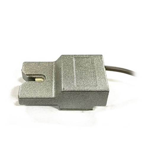
The hardware setup is straightforward. You will need an Arduino board (like the Uno), a stepper motor with a suitable driver (such as the common A4988 or DRV8825), one or more limit switches, and connecting wires. Limit switches are typically mechanical switches with a lever or button. They have three terminals: Common (C), Normally Open (NO), and Normally Closed (NC). For basic homing, we often use the NO configuration. When the switch is not pressed, the circuit is open. When the actuator (the part of your machine that touches the switch) presses the lever, the circuit closes, connecting the Common terminal to the NO terminal.
Connect the stepper motor and its driver to the Arduino following standard practices: the driver's STEP and DIR pins to digital pins on the Arduino, and ensure proper power supply. For the limit switch, connect one side (e.g., the Common terminal) to the Arduino's ground (GND). Connect the other side (the NO terminal) to a digital input pin on the Arduino, for example, pin 2. Then, enable the internal pull-up resistor for that pin in your code. This configuration means the pin will read HIGH when the switch is open and LOW when it is pressed, providing a clear digital signal.
The core logic of the software involves two main states: moving the motor and monitoring the switch. The homing routine typically works like this: the motor is commanded to move slowly in one direction (e.g., towards the physical limit). The code continuously checks the state of the digital pin connected to the limit switch. While the pin reads HIGH (switch open), the motor continues to step. As soon as the pin reads LOW (switch pressed), the motor immediately stops. This position is now defined as the "home" or "zero" position. The motor can then be commanded to move a precise number of steps away from this switch to a known operational starting point.
Here is a simplified code structure to illustrate the homing sequence. It uses the popular AccelStepper library for smooth motor control. First, define the connections and create a stepper object. In the setup function, set the limit switch pin as an INPUT_PULLUP. Then, in the loop, you can initiate the homing function. This function would set a slow speed and a direction towards the switch. A while loop would then step the motor and check the switch state using digitalRead(). Upon detecting a LOW signal, it stops the motor, sets the current position to zero via stepper.setCurrentPosition(0), and perhaps moves the motor slightly away from the switch to disengage. After homing, you can command the motor to any absolute position with confidence.
Implementing limit switches also enables end-stop functionality to prevent over-travel. You can place a switch at both ends of an axis. Your movement code should always check if travel in a given direction is allowed by verifying the corresponding limit switch is not activated before moving. This adds a critical layer of safety. For more complex systems, you might use interrupts. Instead of polling the switch pin in a loop, you can attach an interrupt to it. When the switch is pressed, it triggers an interrupt service routine (ISR) that immediately halts the motor. This provides faster, more reliable response, which is essential for high-speed applications.
In practice, you might encounter switch "bouncing," where the mechanical contacts cause a rapid on-off signal when first pressed. This can be mitigated with a small delay in software after the first detection or by using a simple hardware debounce circuit with a capacitor. Furthermore, consider the mounting of the switch. It must be positioned so that the moving part reliably activates it without excessive force that could bend the lever or damage the mechanism. Often, a small ramp or angled actuator is used to ensure smooth engagement.
By integrating an Arduino, a limit switch, and a stepper motor, you move from open-loop control to a system with a defined reference point. This simple addition dramatically increases the reliability and professionalism of your mechatronics projects. It allows for automated startup sequences, prevents crashes, and is a foundational concept for more advanced techniques like using multiple switches for intermediate positions or implementing soft limits in software. Start by building a simple single-axis homing system; the principles you learn will scale to multi-axis machines, bringing precision and repeatability to your creative and technical endeavors.