check

check

check

check
check
check
check
check

check

check
Integrating a DC motor with an Arduino opens up a world of possibilities for automation, robotics, and precise mechanical control. A common and crucial requirement in such projects is defining the physical boundaries of movement. This is where a limit switch becomes an indispensable component. It acts as a digital sentinel, signaling the Arduino when the motor or its attached mechanism has reached a predefined limit, preventing damage and enabling repeatable operations.
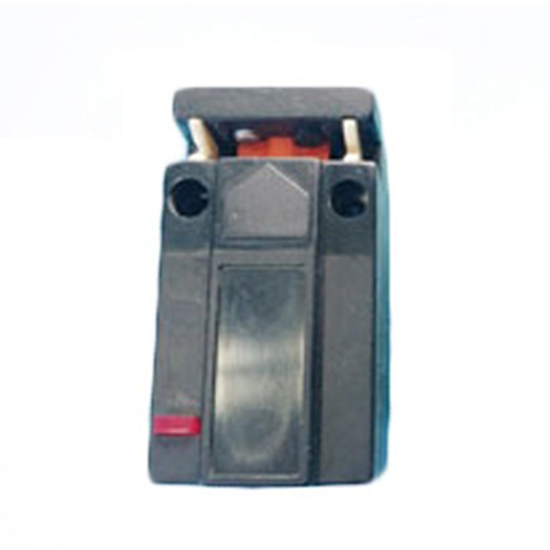
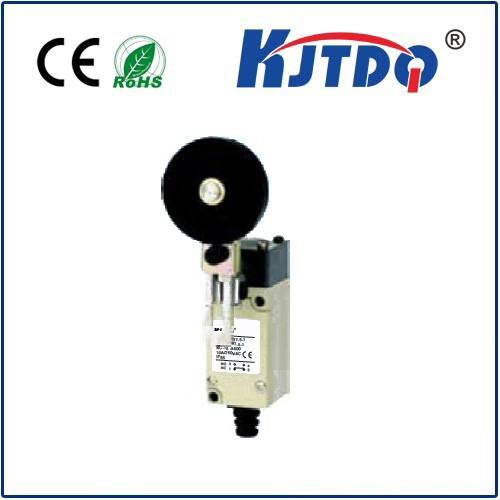
A limit switch is a simple electromechanical device. It typically has a lever or button that, when pressed by a moving part, changes its internal electrical state. In its most common form, it operates like a pushbutton: normally open (NO) or normally closed (NC). For safety in limit detection, a normally closed configuration is often preferred, as a broken wire will simulate a "limit reached" signal, causing the system to halt.
The core principle involves connecting the switch to one of the Arduino's digital input pins. This pin is configured as an INPUT_PULLUP, using the microcontroller's internal resistor. This means the pin reads HIGH when the switch is open (not pressed). When the moving mechanism presses the switch lever, it closes the circuit, connecting the pin directly to ground (GND), causing it to read LOW. The Arduino code continuously monitors this pin's state.
Upon detecting the LOW signal (switch activated), the program logic must immediately command the DC motor to stop. The method for controlling the motor is key. If using a simple transistor circuit, the code would set the motor control pin to LOW. For bidirectional control, an H-Bridge motor driver like the L298N or L293D is essential. These drivers have input pins for direction (IN1, IN2) and enable pins for speed control via PWM.
Here is a practical outline of the steps involved. First, gather the components: an Arduino board (Uno, Nano, etc.), a small DC motor, a compatible motor driver module, a limit switch, jumper wires, and a power supply suitable for the motor. Connect the motor to the output channels of the driver module. Connect the driver's input pins (e.g., IN1, IN2, and ENA) to designated digital pins on the Arduino. Power the driver logic from the Arduino's 5V pin and the motor itself from a separate power source connected to the driver. Connect one terminal of the limit switch to the Arduino's GND. Connect the other terminal to a digital pin (e.g., pin 2), which will be configured with INPUT_PULLUP.
The Arduino sketch revolves around checking the switch state in theloop() function. A robust approach uses anif statement or an interrupt for immediate response. For example:
``cpp
const int switchPin = 2;
const int in1 = 9;
const int in2 = 8;
void setup() {
pinMode(switchPin, INPUT_PULLUP);
pinMode(in1, OUTPUT);
pinMode(in2, OUTPUT);
// Start motor moving towards the switch
digitalWrite(in1, HIGH);
digitalWrite(in2, LOW);
}
void loop() {
if (digitalRead(switchPin) == LOW) { // Switch is pressed
// Stop the motor immediately
digitalWrite(in1, LOW);
digitalWrite(in2, LOW);
// Optional: hold here, reverse after a delay, or trigger another action
delay(1000); // Wait 1 second
// Reverse direction away from the switch
digitalWrite(in1, LOW);
digitalWrite(in2, HIGH);
delay(500); // Reverse for half a second
// Stop again
digitalWrite(in1, LOW);
digitalWrite(in2, LOW);
while(digitalRead(switchPin) == LOW); // Wait until switch is released
}
// Other code can run here
}
``
For more critical applications where missing the switch signal could cause damage, using a hardware interrupt is superior. Pin 2 or 3 on an Arduino Uno can be attached to an interrupt service routine (ISR) that triggers the moment the switch state changes, ensuring near-instantaneous motor cutoff.
In real-world applications, mechanical bounce of the switch contacts can cause erratic readings. Implementing a simple software debounce delay of 10-50 milliseconds after detecting a state change filters out these false triggers. Mounting the switch securely is equally important; its actuator must be positioned so that the moving part presses it reliably at the exact desired limit without excessive force.
This combination of Arduino, DC motor, and limit switch forms the backbone of countless functional projects. Imagine a automated drawer that opens fully and stops, a sliding door that reverses upon encountering an obstacle, a CNC machine axis that accurately homes itself to a known position, or a robot arm that resets to a safe start position. The limit switch provides the essential physical feedback that turns an open-loop motor system into a closed-loop, position-aware mechanism.
Troubleshooting typically involves checking connections with a multimeter, ensuring the switch is actually changing state, and verifying the Arduino pin readings using the Serial Monitor. Remember, the power supply for the motor must be adequate and isolated from the Arduino's logic power to prevent noise or voltage spikes from resetting the microcontroller.
By mastering this fundamental trio of components, you add a critical layer of safety and precision to your mechatronic designs, enabling more reliable and sophisticated automated systems.