check

check

check

check
check
check
check
check

check

check
In the world of industrial automation and heavy machinery, precision and reliability are non-negotiable. At the heart of countless hydraulic systems, from manufacturing presses to construction equipment, lies a critical yet often understated component: the limit switch. Specifically designed for the demanding environments of hydraulic applications, a limit switch serves as the essential sentinel, providing accurate position feedback and ensuring safe, automated control sequences. This guide delves into the vital role, operational principles, and selection criteria for limit switches within hydraulic systems, offering practical insights for engineers and maintenance professionals.
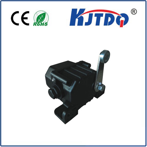
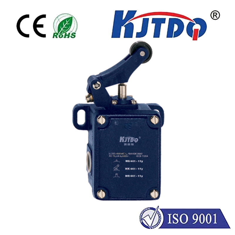
Hydraulic systems generate immense power through pressurized fluid. Controlling the movement of cylinders and actuators—knowing exactly when a piston has reached the end of its stroke or a specific intermediate position—is paramount for both operational efficiency and safety. This is where the hydraulic limit switch excels. It is a robust electromechanical device that detects the presence or position of a moving part within the hydraulic actuator. When the actuator's piston rod or a target attached to it contacts the switch's actuator lever, roller, or plunger, it triggers an internal mechanism. This action changes the state of the switch's electrical contacts, sending a clear signal to the system's programmable logic controller (PLC) or control circuit. This signal can command the hydraulic valve to reverse direction, stop, or initiate the next step in a programmed cycle, preventing over-travel, mechanical damage, or hazardous situations.
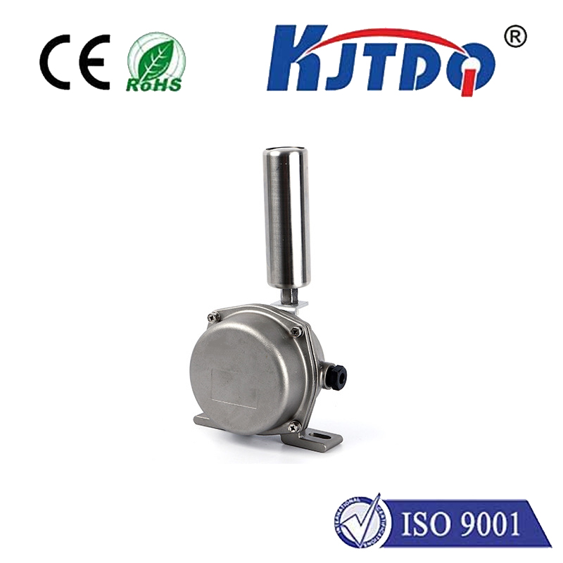
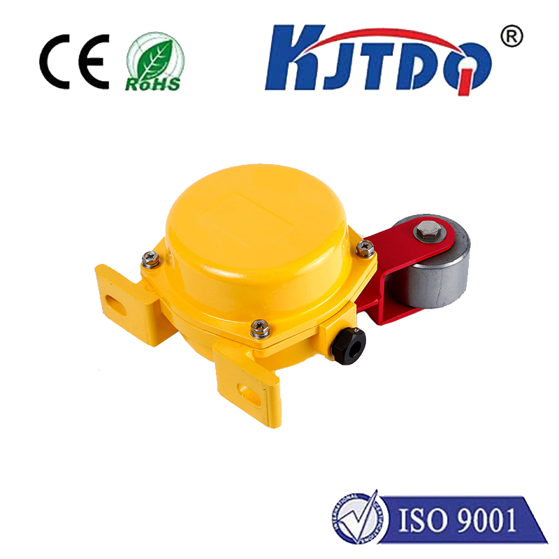
The operational environment of a hydraulic system presents unique challenges, including exposure to vibration, shock, temperature fluctuations, moisture, and potential hydraulic fluid contamination. Therefore, a standard limit switch is often insufficient. Switches designed for hydraulic duty are built with enhanced durability. Key features include:
* Robust Housing: Typically constructed from high-grade metals like stainless steel or ruggedized polymers, offering high ingress protection (IP ratings such as IP67) against dust and water jets.
* Sealed Mechanisms: Internal components are sealed to prevent oil, grease, or coolant ingress, which could cause contact failure or short circuits.
* High-Current Capacity: Capable of handling the inductive loads commonly found in solenoid valve circuits without premature contact wear.
* Variety of Actuators: Options like roller levers, adjustable levers, or push plungers allow for flexible mounting and precise actuation point adjustment to suit different mechanical configurations.
Selecting the correct limit switch for a hydraulic application requires careful consideration of several factors. First, identify the required switching function: simple two-position (on/off) or more complex logic. Next, assess the electrical specifications—voltage, current (AC or DC), and the number of contacts (e.g., SPDT, DPDT). The mechanical interface is crucial; the actuator type must reliably engage with the moving target without binding or misalignment. Environmental ratings are non-negotiable; ensure the switch's IP rating matches or exceeds the exposure to fluids and particulates. Finally, consider the mounting style—side-mounted, front-mounted, or with a specific bracket—to ensure a secure and accessible installation on or near the hydraulic cylinder.
Beyond basic position detection, modern hydraulic limit switches contribute significantly to system intelligence and predictive maintenance. By monitoring the consistency of switch actuation timing, operators can infer the health of the hydraulic system. For instance, a gradually slowing cylinder stroke might indicate pump wear or a developing leak. Integrating these switches into a networked control system allows for real-time monitoring and data logging, forming the foundation of Industry 4.0 applications in fluid power systems.
Proper installation and routine maintenance are key to longevity. Ensure the switch is mounted securely to minimize vibration-induced stress. The actuator should engage smoothly without excessive force or shock loading. Regularly inspect the switch housing for physical damage, check the tightness of electrical connections, and verify the actuator moves freely without obstruction. For switches in extremely dirty or wet conditions, more frequent inspections are advisable.
In conclusion, the limit switch is far more than a simple component in a hydraulic system; it is a fundamental pillar of controlled motion, operational repeatability, and personnel safety. By understanding its function, specifying the right model for the environmental and electrical demands, and implementing a basic maintenance protocol, engineers can dramatically enhance the reliability, efficiency, and lifespan of their hydraulic machinery. In an era where downtime is costly and safety is paramount, investing in high-quality, application-specific limit switches is not just a technical decision, but a strategic one for sustainable operations.