
check

check

check

check

check

check

MOTION MONITORING · PRODUCT STORY
"Motor Started" Does Not Equal "Equipment Running Normally"
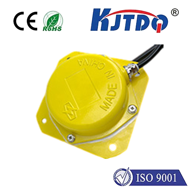
KJT-11801 Intelligent Speed Switch
From the drive end to the actuator end, adding a layer of true operation confirmation for rotating equipment.
SPEED RANGE: 1–200 r/min
RESPONSE TIME: < 2 ms
PROTECTION RATING: IP66
A motor running only indicates that power has been delivered;
only the continuous rotation of the monitored shaft proves that mechanical transmission has truly taken place.
A Control Cabinet Displaying "RUNNING" Does Not Mean the Transmission End Is Working Properly
In continuously operating machinery such as belt conveyors, bucket elevators, and feeders, the motor may have started, and contactors or frequency drives may display normal status. However, due to belt slippage, disconnected chains, fractured drive shafts, or mechanical jamming, the driven shaft may already have slowed down abnormally or stopped completely.
If the control system only reads motor start/stop signals, it cannot verify whether power is truly reaching the mechanical terminal. By the time material build-up, line interruption, or abnormal noises are detected, the failure has often expanded:
The motor continues to rotate while the driven shaft has completely stopped;
Belts or chains slip, leaving equipment idling or operating at low efficiency;
Broken shafts or failed couplings occur without triggering an immediate electrical alarm;
Manual inspections cannot reliably cover long-distance, multi-equipment, and continuous production lines.
Product Summary in One Sentence:
The intelligent speed switch directly monitors the rotational status of the target shaft and outputs a switching signal whenever abnormal deceleration or stalling reaches preset conditions.
Focusing on Hidden Faults Where the "Motor Spins, But the Machine Doesn’t"
| Anomaly Type | Nature of Fault | Field Manifestation |
| Belt Slip | Asynchrony between pulley and conveyor belt | Speed drops, reduced carrying capacity, localized friction heating |
| Chain / Belt Disconnection | Power cannot be transmitted downstream | Motor idles freely; actuator mechanisms stop |
| Shaft / Coupling Fracture | Decoupling between upstream and downstream motion | Control panel displays "Running"; mechanical execution fails |
| Mechanical Stall / Jam | Abnormal load or foreign objects obstructing movement | Shaft speed drops sharply or halts entirely |
| Abnormal Slowdown | Equipment still moves, but below process speed | Uneven feeding, rhythm disruption, decreased throughput |
Four Core Pain Points Solved:
Unverified Running Status: Knowing only that the motor has started, but blind to whether the mechanical terminal is actually moving.
Delayed Fault Detection: Belt slip or broken shafts do not always trigger conventional electrical overload protections immediately.
Limited Inspection Coverage: Manual checks cannot provide continuous, real-time supervision across distributed machinery.
Lack of Interlocking Action: Without clear switching signals, the PLC/control system cannot trigger timely alarms or automated shutdowns.
Monitoring Boundary: Speed switches confirm rotation, underspeed, and stall conditions; they are not equivalents to torque, temperature, or mechanical overload sensors. A comprehensive protection scheme should configure multi-tiered safeguards according to equipment risk.
Upgrading from "Issuing an Operation Command" to "Confirming Mechanical Execution"
Direct Mechanical Monitoring: Targets the actual shaft rather than relying solely on electrical signals, reflecting actual machine motion.
Earlier Anomaly Ingestion into Control: Translates slow rotation, underspeed, and stoppage into explicit status signals, minimizing fault exposure time.
Non-Contact Detection: The sensing head and target flag require no physical friction, reducing mechanical wear and seizure risks.
Easy-to-Integrate Switching Output: Easily wired into PLCs, relays, annunciators, or trip interlock circuits once voltage and load ratings are matched.
Multiple Power Supply Options: Available in 24 VDC, 110 VAC, and 220 VAC configurations to suit both new installations and retrofits.
IP66 Industrial Protection: Designed for common dust, moisture, and water-spray environments (not intended for continuous submersion).
A Complete Status Interlocking Chain:
01 Detect Rotation ➔ 02 Evaluate Status ➔ 03 Output Signal ➔ 04 Trigger Alarm / Interlock
| Equipment Type | Recommended Sensing Point | Primary Monitoring Purpose |
| Belt Conveyors | Drive pulley or tail pulley | Detecting slip, underspeed, and stoppage |
| Bucket Elevators | Tail shaft or idler shaft | Broken chain, jamming, and underspeed monitoring |
| Screw Conveyors | End shaft or driven shaft | Jamming and stall detection |
| Chain Conveyors | Driven sprocket shaft | Chain jump, breakage, and transmission failure |
| Feeders & Batching Units | Actuator rotating shaft | Low speed, stall, and cycle irregularities |
| Mixers & Agitators | Shaft representing terminal motion | Operation verification and auxiliary interlocking |
Installation & Commissioning Checklist:
Ensure the target flag surface is parallel to the sensing face of the probe;
Maintain sensing gap $H_2 \le 8\text{ mm}$ (a nominal $4\text{ mm}$ gap is recommended);
Use a mounting bracket with sufficient rigidity to prevent vibration-induced gap variations;
Ensure a clearance $H_1 \ge 20\text{ mm}$ from metallic bases to minimize magnetic interference from surrounding metals;
Test and verify all states during commissioning: starting, normal operation, abnormal slowdown, and full stop.
Application Boundary: For applications involving personal safety or catastrophic machine risks, the speed switch must not be the sole protective device. It should form a layered interlocking architecture alongside E-stops, belt drift switches, chute plugging detectors, overload trips, and pull-cord switches.