check

check

check

check
check
check
check
check

check

check
In industrial automation and process control systems, limit switches play a crucial role in monitoring and controlling the position of machinery. The Topworx DXP series stands out as a reliable and versatile solution for demanding applications. This manual provides a comprehensive overview of the Topworx DXP limit switch, covering its features, installation, operation, and maintenance to ensure optimal performance and system safety.
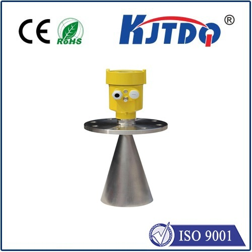
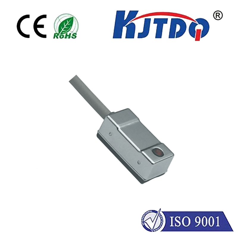
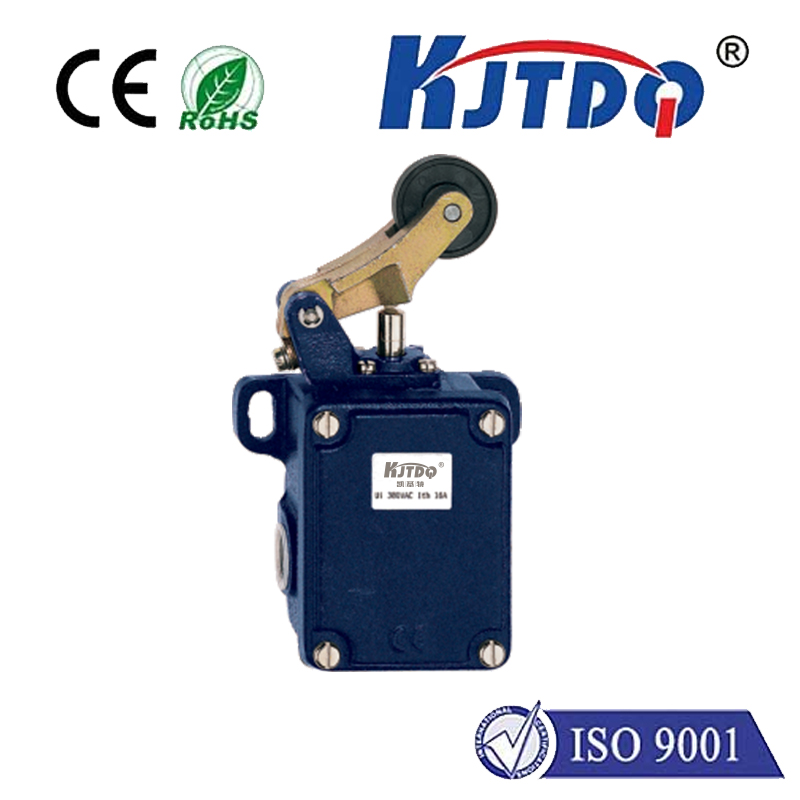
The Topworx DXP limit switch is engineered for durability and precision in harsh environments. Its robust housing, typically constructed from materials like stainless steel or engineered polymers, offers excellent resistance to corrosion, moisture, and physical impact. This makes it suitable for a wide range of industries, including oil and gas, chemical processing, water treatment, and manufacturing. The switch incorporates a high-quality actuator mechanism designed for millions of reliable cycles, ensuring long-term operational stability and reducing downtime.
A key feature of the DXP series is its modular design. Users can often select from various actuator types (such as roller lever, plunger, or whisker) and electrical configurations to match specific application requirements. This flexibility allows for precise positioning feedback for valves, doors, conveyors, and other moving equipment. The electrical compartment is sealed to prevent ingress of contaminants, with clear terminal markings for straightforward wiring. Many models also offer visual indicators, like a brightly colored flag, to provide at-a-glance status confirmation from a distance.
Proper installation is fundamental to the switch's functionality and lifespan. The process begins with selecting the correct mounting location. It should be positioned so that the actuator makes positive contact with the target machine part without being over-traveled or subjected to excessive force. The mounting surface must be clean, flat, and secure. Use the appropriate hardware, as specified in the official Topworx DXP documentation, to fasten the switch body firmly. Care should be taken to route cables away from sharp edges, heat sources, or moving parts to prevent damage. Conduit entries should be properly sealed to maintain the unit's ingress protection rating.
Wiring the Topworx DXP limit switch requires adherence to local and national electrical codes. Always disconnect power before making any electrical connections. Identify the switch's contact configuration—whether it is normally open (NO), normally closed (NC), or a combination—as per your control circuit design. Connect the wires to the correctly labeled terminals, ensuring tight and secure connections. For switches with multiple poles or SPDT configurations, double-check the wiring diagram provided with the specific model. After wiring, perform a continuity test with a multimeter to verify the contacts open and close as expected when the actuator is manually operated.
Operation of the DXP limit switch is straightforward. As the target machine component moves, it engages the switch's actuator. This mechanical action internally changes the state of the electrical contacts, sending a signal to the programmable logic controller (PLC) or other control device. This signal is used to confirm a position (e.g., "valve fully open" or "door closed"), initiate a subsequent action in a sequence, or trigger a safety interlock. The switch is designed for repetitive, accurate operation. Operators should regularly listen for a clean, crisp "click" sound during actuation, which indicates proper mechanical function.
Routine maintenance is minimal but essential for sustained reliability. A periodic visual inspection should check for any signs of physical damage, corrosion, or loose mounting hardware. Ensure the actuator moves freely without binding or obstruction. In dusty or dirty environments, gently clean the exterior of the switch and the actuator area to prevent buildup that could impede movement. Do not use high-pressure water or harsh chemicals that could compromise seals. It is also prudent to periodically verify the electrical operation by checking the output signal at the control panel matches the physical position of the actuator. Any switch showing signs of erratic behavior, physical damage, or electrical failure should be replaced immediately with a genuine Topworx DXP part to maintain system integrity.
Understanding the manual and specifications for your specific Topworx DXP model is paramount. Always refer to the official technical data sheets and installation instructions provided by Topworx or its authorized distributors. These documents contain model-specific details regarding torque settings, electrical ratings, temperature ranges, and agency approvals (such as ATEX, IECEx, or CSA). Following these guidelines ensures not only the optimal performance of the limit switch but also the overall safety and efficiency of the automated system it serves. By implementing proper installation, operation, and maintenance practices as outlined, the Topworx DXP limit switch will deliver consistent and dependable service as a critical component in industrial control loops.