rpm meter with proximity sensor
- time:2025-06-24 01:42:15
- Click:0
Unlocking Precision: The Power of RPM Meters with Proximity Sensors
Imagine monitoring the critical rotational speed of a high-performance engine, a massive industrial turbine, or even delicate laboratory equipment without ever touching the spinning shaft. This is the remarkable capability offered by RPM meters integrated with proximity sensors. This combination represents a leap forward in non-contact tachometry, providing unparalleled accuracy, safety, and versatility for professionals across countless industries. Understanding this technology is key to optimizing machinery monitoring, predictive maintenance, and operational efficiency.
Beyond Mechanical Contact: The Core Principle
Traditional contact-based tachometers require physical interaction with the rotating component, typically using an encoder wheel, a rubber-tipped probe, or a mechanical coupling. While effective in some scenarios, contact introduces significant limitations:
- Wear and Tear: Physical contact inevitably causes friction, leading to sensor and target surface degradation over time.
- Safety Hazard: Contacting high-speed or hazardous machinery poses risks to personnel and equipment.
- Intrusiveness: Mounting contact sensors can be difficult or impossible in confined spaces or on delicate components.
- Speed Limitations: Mechanical inertia and slippage limit the maximum measurable speeds.
The RPM meter with proximity sensor eliminates these drawbacks. It fundamentally works by:

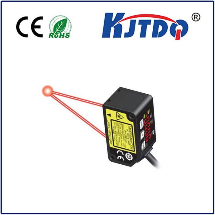
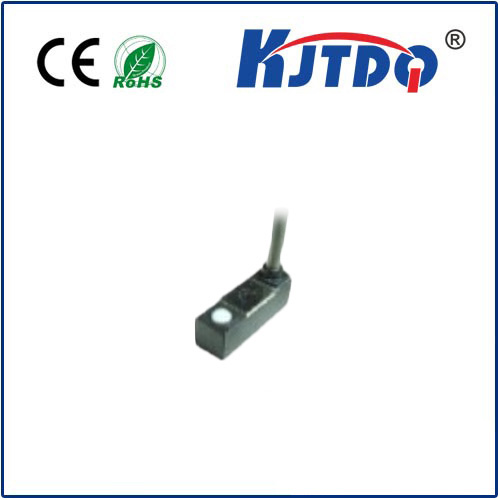
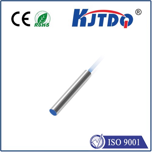
- Detecting Presence: A proximity sensor (inductive, capacitive, photoelectric, or magnetic) is positioned near the rotating target but not physically touching it.
- Sensing Targets: The target can be a specially added element (like a gear tooth, keyway, or reflective tape) or an inherent feature of the shaft/rotor itself (e.g., a bolt head).
- Generating Pulses: As each target passes the sensor, it triggers a distinct electronic pulse. Inductive sensors react to metallic discontinuities via eddy currents, photoelectric sensors detect changes in reflected light, and magnetic sensors respond to variations in a magnetic field.
- Calculating RPM: The integrated RPM meter electronics precisely count these pulses over a defined time period (e.g., seconds or fractions of a second). By measuring the frequency of these pulses, the meter accurately calculates Revolutions Per Minute (RPM). The formula is essentially:
RPM = (Pulses counted per time interval) / (Number of targets per revolution) * (60 / Time interval in seconds).
Why Choose a Proximity-Based RPM Meter? Key Advantages
The synergy of the proximity sensor and the digital RPM counter delivers compelling benefits:
- Non-Contact Operation: The single most significant advantage. It enables safe measurement of high-speed, extremely hot, electrically charged, or otherwise inaccessible rotating parts. There’s zero risk of mechanical wear to the sensor or the target, ensuring long-term reliability and accuracy.
- High Accuracy and Wide Range: Modern electronics provide exceptional pulse-counting precision. These instruments can measure speeds ranging from very low RPMs (useful for startup/stall detection) up to hundreds of thousands of RPMs, far exceeding the capability of most contact methods. Accuracy is often within ±0.01% or better.
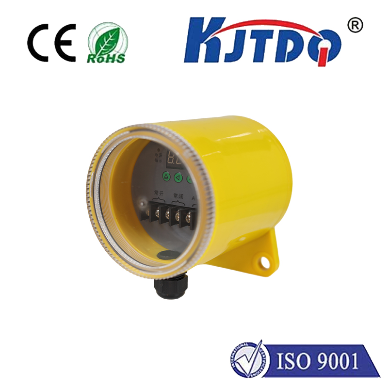
- Robustness: Proximity sensors are inherently durable. Suitable housings (often IP67 or higher) protect them from harsh industrial environments, including dirt, dust, moisture, oil, and vibration. They are less susceptible to shock damage compared to contact probes.
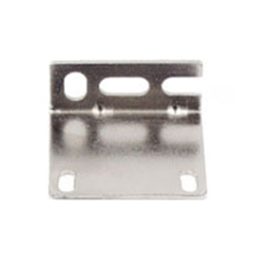
- Minimal Setup Intrusion: Mounting the small sensor head is usually straightforward, requiring only a stable bracket near the target. This minimizes system disruption compared to installing complex encoders.
- Versatility: Different sensor types cater to various applications:
- Inductive: Ideal for ferrous metals (steel, iron).
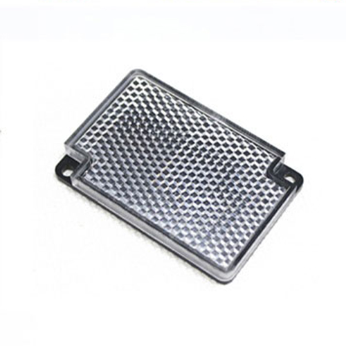
- Photoelectric (Reflective): Effective for non-metallic targets or metallic ones with reflective tape.
- Magnetic: Detects magnets embedded in or attached to the target.
- Data Logging and Analysis: Many modern digital RPM meters feature data hold, min/max recording, analog outputs (4-20mA, 0-10V), and even connectivity (USB, Bluetooth, RS-232) for integration into PLCs, SCADA systems, or computer-based monitoring and diagnostics.
Where is this Technology Essential? Diverse Applications
RPM meters with proximity sensors are indispensable tools wherever non-intrusive, reliable rotational speed monitoring is needed:
- Industrial Manufacturing: Monitoring motors, pumps, compressors, fans, conveyor drives, gearboxes, and spindles on CNC machines for process control, efficiency optimization, and predictive maintenance (detecting abnormal speed deviations indicating wear or misalignment).
- Automotive & Aerospace: Dynamometer testing, turbocharger speed verification, propeller/RPM synchronization checks, engine performance analysis.
- Energy & Power Generation: Turbine monitoring (steam, gas, hydro, wind), generator speeds, ensuring safe operating limits.
- Petrochemical & Heavy Industry: Monitoring critical rotating assets in refineries, chemical plants, and drilling rigs where safety and reliability are paramount.
- Laboratories & Research: Precise speed control and measurement for centrifuges, mixers, test rigs, and prototype development.
- Marine: Engine RPM monitoring, thruster control, propeller shaft speeds.
- Maintenance & Reliability Departments: Portable, handheld versions are essential for technicians performing vibration analysis, balancing, and condition-based maintenance routes.
Selecting the Right RPM Meter with Proximity Sensor
Choosing the best instrument for your needs involves considering several factors:
- Target Material & Size: What is the rotating target made of (steel, aluminum, plastic)? How large are the features you’ll be detecting (e.g., teeth, keyways)? This dictates the sensor type (inductive, photoelectric, magnetic) and its required sensing distance/sensitivity.
- Required Speed Range: Ensure the instrument covers your minimum and maximum anticipated RPMs.
- Accuracy & Resolution: Determine the level of precision needed for your application. High-precision research often demands higher resolution than general industrial monitoring.
- Number of Pulses Per Revolution: How many targets pass the sensor per full rotation? This is critical for the RPM calculation. Setting this parameter correctly in the meter is vital.
- Environmental Conditions: Consider temperature extremes, presence of chemicals, dust, moisture, or strong electromagnetic fields. Choose sensors and meters with appropriate ingress protection (IP) ratings.
- Output Requirements: Do you need just a digital display? Analog outputs for control systems? Data logging? Digital communication interfaces?
- Mounting Constraints: Physically, how and where can you mount the sensor head near the target? Fixed or portable application?
Installation and Best Practices
Proper installation is crucial for optimal performance:
- Sensing Distance: Follow the manufacturer’s specifications for the nominal sensing distance relative to your specific target. A common rule of thumb for inductive sensors is installing 75-90% of the rated distance for maximum stability. Too far reduces signal strength; too close risks physical damage (despite non-contact).
- Target Approach: Ensure the target passes perpendicularly across the active face of the sensor for the strongest signal.
- Mounting Rigidity: Vibration can cause fluctuating distance between sensor and target, leading to measurement errors or false triggers. Use sturdy brackets.
- Avoid Electrical Noise: Route sensor cables away from high-power cables or motors. Use shielded cables and ground the shielding properly as per the instrument manual.
- Correct Setup: Accurately input the number of pulses per revolution into the RPM meter. Calibration against a known reference is recommended for critical applications.
By harnessing the power of non-contact sensing, RPM meters equipped with proximity sensors provide a robust, accurate, and