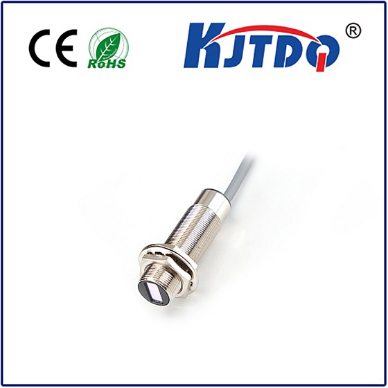
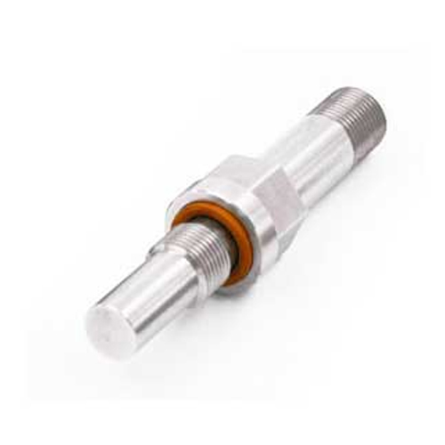
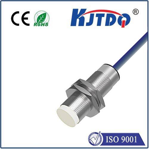
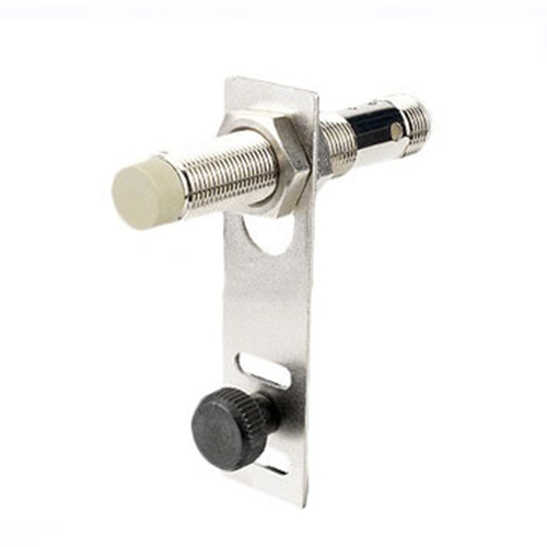
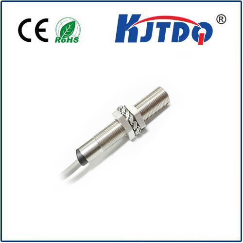
rpm proximity sensor
- time:2025-06-24 01:47:23
- Click:0
Unlocking Precision: The Essential Guide to RPM Proximity Sensors for Rotation Monitoring
Imagine a critical motor in a manufacturing line suddenly failing, halting production for hours and costing thousands in lost revenue and repairs. Often, such catastrophic failures stem from undetected changes in rotational speed – subtle shifts that, if caught early, could have been prevented. This is where RPM Proximity Sensors step into the spotlight. Far more than just simple counters, these sophisticated devices are the frontline guardians of machinery health, providing the precise, real-time rotational speed data essential for operational efficiency and predictive maintenance across countless industries.
Understanding the Core Concept: Measuring Revolutions Per Minute Without Contact
At its essence, an RPM proximity sensor is a non-contact electronic device designed specifically to detect the rotational speed (Revolutions Per Minute) of a target, typically a rotating shaft or gear. Unlike mechanical tachometers that require physical contact, proximity sensors work by sensing the presence or passing of a metallic target without touching it. This fundamental characteristic of non-contact sensing is crucial. It eliminates friction, wear, and potential damage to both the sensor and the rotating component, ensuring long-term reliability and accuracy in demanding environments laden with vibration, oil, dust, or extreme temperatures.
How Does an RPM Proximity Sensor Work? The Magic of Eddy Currents and Hall Effect

The most common technologies powering RPM proximity sensing are inductive proximity sensors and Hall Effect sensors, each operating on distinct physical principles:
- Inductive Proximity Sensors (Eddy Current Principle):
- These sensors generate a high-frequency oscillating electromagnetic field from an internal coil.
- When a ferrous (iron-containing) metal target (like a bolt head, gear tooth, or dedicated notch on a shaft) enters this field, it induces small circulating electrical currents called eddy currents within the target.
- These eddy currents draw energy from the sensor’s internal oscillator circuit, reducing its oscillation amplitude.
- The sensor’s internal circuitry detects this amplitude change and triggers a solid-state switch output (typically PNP or NPN). Each passing target results in one output pulse.
- Key Point: Speed calculation comes from measuring the frequency of these output pulses. If a shaft has 6 targets (like bolt heads) and the sensor outputs 100 pulses per second, the RPM = (100 pulses/sec * 60 seconds/minute) / 6 targets = 1000 RPM.
- Hall Effect Sensors:
- These sensors detect changes in a magnetic field using a semiconductor element (the Hall element).
- A permanent magnet is either embedded within the sensor or positioned opposite it on the rotating component. Alternatively, magnets can be mounted directly on the target shaft.
- As a magnetic target (or a ferrous target passing near the magnet) moves past the sensor, it disturbs the magnetic field lines.
- This disturbance causes a proportional voltage change (the Hall voltage) across the semiconductor element.
- Internal circuitry processes this signal to produce a clean digital pulse output for each magnetic event detected.
- Key Point: Hall Effect sensors excel at detecting magnetic fields and are often preferred for very low-speed detection or applications requiring precise position alongside speed. They are also suitable for sensing non-ferrous metals like aluminum if magnets are attached.
Beyond Simple Counts: The Indispensable Applications of RPM Monitoring
The ability to accurately measure rotational speed is fundamental to modern industrial processes. RPM proximity sensors serve as critical components in a vast array of applications:
- Predictive Maintenance (PdM): This is arguably their most significant role. Monitoring motor, pump, fan, turbine, and gearbox speeds provides vital health indicators.
- Deviations from normal operating speed can signal developing problems like bearing wear, misalignment, imbalance, belt slippage, lubrication issues, or impending bearing failure.
- Continuous RPM monitoring allows maintenance teams to schedule interventions proactively, preventing catastrophic failures and unplanned downtime – a massive cost saver.
- Motor & Drive Control: Ensuring motors operate at their designated speed is crucial for process consistency (speed monitoring). Sensors provide the speed feedback required for precise closed-loop control systems (Variable Frequency Drives - VFDs), enabling smooth ramping up/down and maintaining setpoints under varying loads.
- Conveyor & Material Handling: Monitoring the speed of rollers, pulleys, and drives ensures consistent material flow, detects jams or slippage (overspeed or underspeed detection), and verifies synchronization between different conveyor sections.
- Turbine & Engine Monitoring: In power generation, aviation, and heavy machinery, RPM sensors are vital for monitoring turbine shaft speeds and engine crankshaft/camshaft speeds, ensuring they operate within safe limits and providing critical data for control and protection systems.
- Process Control: Speed measurements are essential in applications like mixing, blending, cutting, winding, and printing, where the rotational speed directly impacts product quality and consistency.
- Safety Systems: Implementing overspeed detection guards (using RPM proximity sensors) is a critical safety function on elevators, cranes, centrifuges, and high-speed spindles, triggering immediate shutdowns to prevent dangerous situations.
- HVAC Systems: Monitoring fan speeds in large commercial systems ensures efficient airflow and allows for fault detection.
Why Choose Proximity Sensors for RPM? Key Advantages Resonate
The dominance of proximity sensors for RPM measurement stems from compelling advantages:
- Non-Contact Operation: Eliminates wear and tear, enhances longevity, and allows measurement on delicate or inaccessible components.
- High Reliability & Robustness: Built with industrial-grade enclosures (often stainless steel), they withstand harsh environments – vibration, moisture, contaminants, and extreme temperatures.
- High Accuracy & Resolution: Capable of detecting very high speeds and providing precise measurements based on pulse frequency, essential for control and diagnostics.
- Wide Speed Range: Modern sensors can accurately measure from very low RPMs (even fractions of an RPM with Hall Effect and sufficient targets) up to tens of thousands of RPM.
- Immunity to Contaminants: Unlike optical encoders, they are largely unaffected by dirt, dust, oil, or fog that could obscure a light path.
- Simplified Installation: Often mounted externally near the target with minimal mechanical integration required, simplifying retrofits and maintenance.
- Output Versatility: Provide standardized electrical output signals (digital pulses, 4-20mA analog proportional to speed) easily interfaced with PLCs (Programmable Logic Controllers), SCADA systems, DCSs (Distributed Control Systems), and dedicated tachometers/controllers.
Selecting the Right Sensor: Inductive vs. Hall Effect - A Matter of Target & Requirement
Choosing between an inductive sensor and a Hall Effect sensor hinges on specific application parameters:
- Target Material: Use inductive sensors for detecting ferrous metal (steel, iron) targets without magnets. Use Hall Effect sensors for detecting magnetic fields directly or ferrous targets if magnets are attached (enabling them to sense non-ferrous rotating parts).
- Required Sensing Distance: Inductive sensors typically


