inductive sensor distance
- time:2025-06-20 01:44:04
- Click:0
Inductive Sensor Distance: Mastering Range, Placement, and Performance
Imagine a robotic arm flawlessly assembling an engine block. Its movements are precise, but a collision with a metal component could be catastrophic. Hidden within its joints lie silent sentinels: inductive sensors. Their critical job? Detecting the presence of metal parts without touching them, governed by one crucial parameter: distance. Understanding inductive sensor distance isn’t just technical jargon; it’s fundamental to unlocking reliability, safety, and peak performance in countless automated systems.
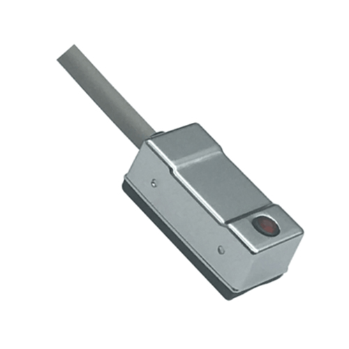
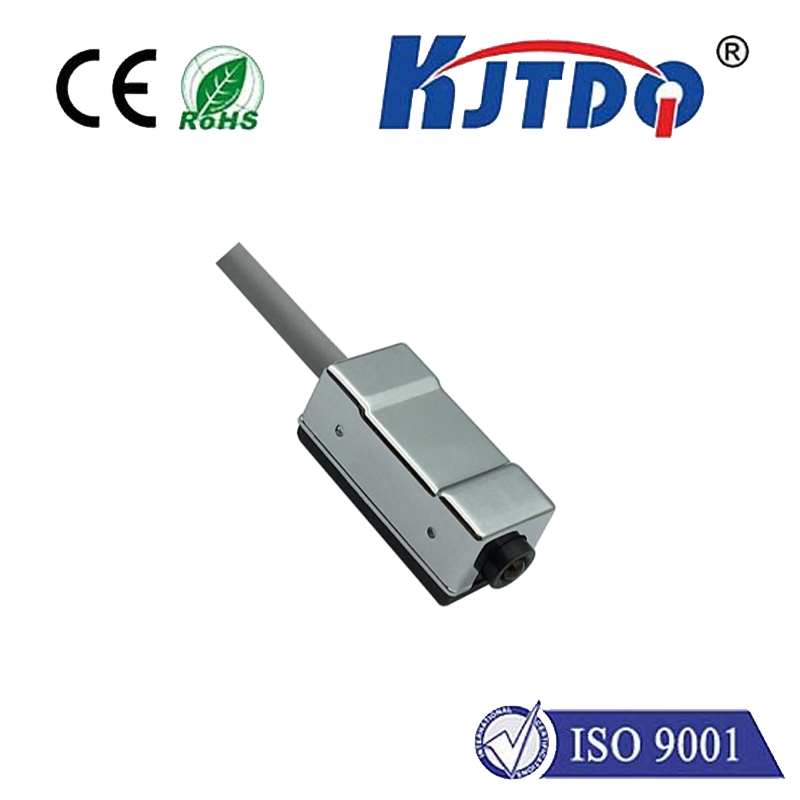
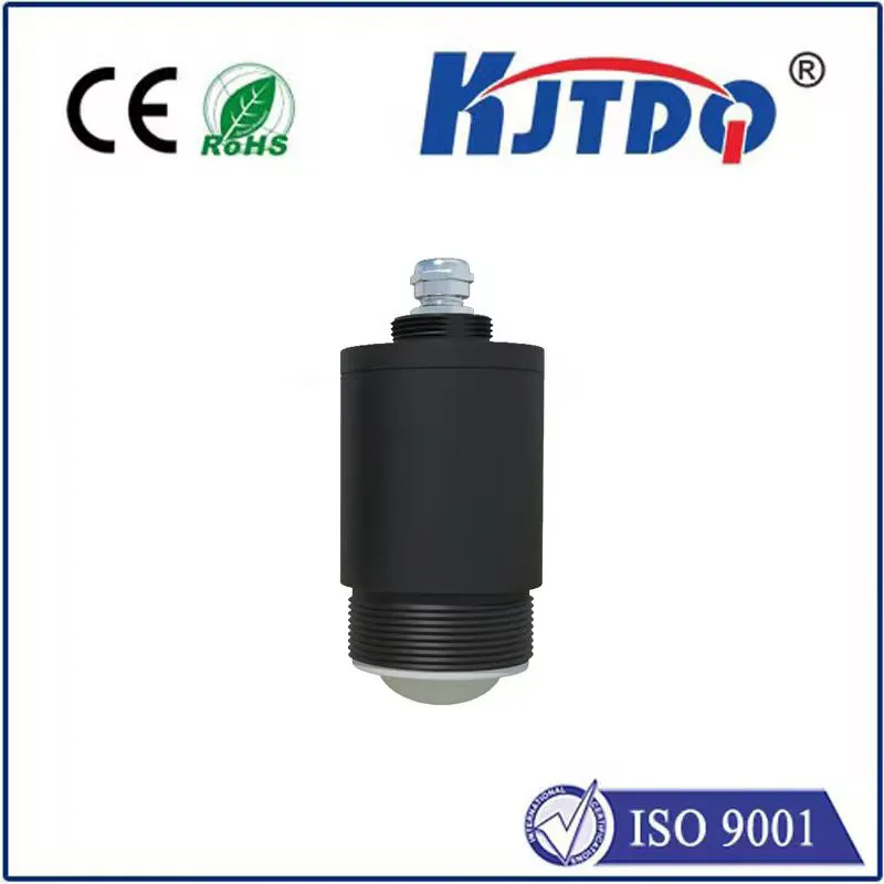
Inductive proximity sensors are the workhorses of industrial automation. Operating on the principle of electromagnetic induction, they generate a high-frequency oscillating magnetic field from their active face. When a ferrous (iron-based) or non-ferrous (like aluminum or copper) metal target enters this field, eddy currents are induced within the target. These eddy currents draw energy from the sensor’s oscillating circuit, causing a measurable change (typically a drop in amplitude or change in frequency). The sensor’s electronics detect this change and trigger an output signal, indicating the target’s presence.
Operating Distance: The Core Specification

The heart of “inductive sensor distance” lies in its nominal sensing distance (Sn). This standardized value, specified by the manufacturer (e.g., 5mm, 8mm, 15mm), represents the theoretical detection range under ideal laboratory conditions (usually a square mild steel target measuring 1mm x Sn x Sn, at room temperature). It’s the benchmark for comparison.
However, Sn is just the starting point. Several critical factors influence the real-world achievable sensing distance:
- Target Material: Ferrous metals (like mild steel) induce stronger eddy currents and are detected at greater distances. Non-ferrous metals like aluminum or copper are less “detectable,” often requiring sensors specifically designed for them or resulting in a reduced sensing range (typically 60-80% of Sn for aluminum, 20-40% for copper). Stainless steel also generally requires a reduction factor.
- Target Size and Shape: The standard Sn assumes a specific target size. Smaller targets, or targets with complex shapes that don’t fully interact with the magnetic field, will be detectable at a shorter distance. A rule of thumb: the target should ideally be at least equal to the sensor’s face diameter and flat.
- Temperature: Extreme temperatures, both high and low, can slightly alter the properties of the sensor’s coil and electronics, potentially leading to minor variations in sensing distance.
- Voltage Fluctuations: Significant variations in the sensor’s supply voltage can sometimes impact its sensitivity and thus its effective range.
- Sensor Face Configuration: Standard sensors have a sensing field projecting directly from the front face. Shielded sensors have a metallic housing surrounding the coil, concentrating the magnetic field axially in front of the face. While protecting against adjacent metal, this also reduces the sensing distance compared to an unshielded sensor of the same nominal rating. Unshielded sensors have a larger, more lateral sensing field, offering longer range but requiring more careful mounting to avoid interference from surrounding metal.
Installation Distance: The Practical Reality
Knowing the theoretical sensing range is only half the battle. The installation distance – the actual physical gap between the sensor’s active face and the target object when it’s detected – is paramount for reliable operation.
- Critical Practice: Always derate the nominal sensing distance (Sn) for real-world conditions. A common industry recommendation is to utilize only 60-80% of the Sn value during installation. This derating accounts for material variations, temperature effects, voltage tolerances, and ensures consistent operation even as components experience normal wear or slight misalignment over time. Relying solely on Sn risks intermittent failures or missed detections.
- Mounting Considerations: For shielded sensors, embedding them in metal (flush mounting) is generally acceptable and often preferred, as their field is focused forward. Unshielded sensors, with their larger lateral field, must have a clearance zone (usually specified by the manufacturer, e.g., 1x Sn radially) around their sides to prevent false triggering from the mounting bracket itself.
- The “Dead Zone”: Interestingly, there’s a very short zone immediately in front of the sensor face where detection might be unreliable. While targets are usually detected right up to the face in practice, understanding the sensor’s specific characteristics helps avoid installation right on the theoretical detection limit.
Optimizing Performance Through Distance Management
Getting the distance right directly impacts system efficiency and uptime. Here’s how to manage it effectively:
- Know Your Target: Precisely identify the material (ferrous, non-ferrous type) and the minimum size/shape of the target you need to detect. Consult reduction factor tables from sensor datasheets.
- Calculate Usable Range: Apply the appropriate reduction factor for your target material to Sn. Then, apply the 60-80% derating factor to this reduced value to determine your safe installation distance. Example: For an Sn=10mm sensor detecting aluminum (reduction factor 0.7), usable range is 7mm. Derating to 70%, the recommended max installation gap is ~5mm.
- Precision Calibration: For critical applications requiring maximum accuracy, the *triangular test method* is highly recommended. This involves:
- Mounting the sensor and target on adjustable slides forming two sides of a triangle.
- Slowly moving the target towards the sensor along the hypotenuse.
- Precisely measuring the point where the sensor reliably triggers.
- Repeating across multiple points to map the exact detection profile.
- Consider Environment: Factor in potential temperature swings or vibration that could affect the gap. Choose sensors rated for the environment and allow extra margin if needed.
- Select the Right Sensor Type: Do you need the longer range of an unshielded sensor (and have the mounting clearance)? Or the robustness and flush-mounting capability of a shielded sensor with a slightly shorter range? Choose based on mechanical constraints.
From ensuring a car door is fully latched before driving, to verifying a metal part is correctly positioned before a welding robot fires, to counting bottles on a high-speed line, inductive sensors silently perform millions of detections daily. Their effectiveness hinges critically on the precise management of inductive sensor distance. By deeply understanding the interplay between nominal range, target characteristics, derating principles, and careful installation, engineers and technicians can design and maintain systems where detection is consistently reliable. Mastering this invisible gap is the key to robust automation, minimizing downtime, and ensuring processes run smoothly and safely – a testament to the profound impact of getting just a few millimeters right.