check

check

check

check
check
check
check
check

check

check
In industrial automation, the seamless integration of various components is paramount for efficient and reliable system operation. Among these critical components, the limit switch plays a fundamental role, especially when interfaced with a Programmable Logic Controller (PLC). This article delves into the function, application, and integration of limit switches within PLC-controlled environments, providing a clear perspective for engineers and technicians.
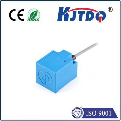
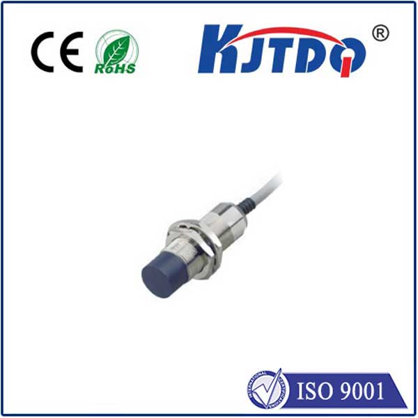
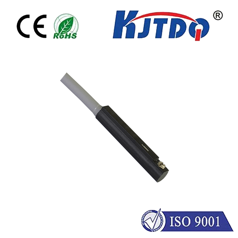
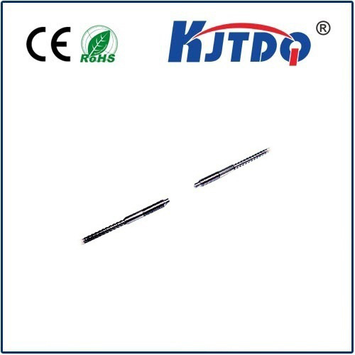
A limit switch is an electromechanical device designed to detect the presence or absence of an object, or to monitor the limits of mechanical motion. It operates on a simple principle: a physical actuator (like a lever, roller, or plunger) is triggered by an object's movement. This action opens or closes a set of electrical contacts within the switch, thereby changing its output state. This binary signal—either ON (closed circuit) or OFF (open circuit)—serves as a crucial input for control systems.
The true power of a limit switch is unlocked when connected to a PLC. A PLC is an industrial digital computer adapted for the control of manufacturing processes. It continuously monitors inputs from sensors like limit switches, processes this data according to a user-written program, and then controls outputs to actuators such as motors, valves, or lights. The limit switch provides the PLC with precise, real-time positional data. For instance, in a conveyor belt system, a limit switch can signal the PLC when a product reaches the end of a specific zone. The PLC program can then instantly command a robotic arm to pick up the product or instruct the conveyor to stop.
The integration process is straightforward. The limit switch is wired to one of the PLC's discrete input modules. When the switch is actuated, it sends a voltage signal (e.g., 24V DC) to this input point. The PLC's input module detects this voltage change and updates the corresponding memory bit in its data table from a 0 (false) to a 1 (true). The control programmer writes logic, often using ladder logic diagrams, that references this input bit. A simple command might be: "IF Input_I0.1 (from limit switch) is TRUE, THEN energize Output_Q0.0 (to start a motor)."
Common applications of limit switches in PLC systems are extensive. They are indispensable for providing end-of-travel detection for moving parts like machine tool slides, elevator cars, or garage doors, preventing mechanical damage by signaling the PLC to halt motion. They are used for part positioning and sequencing in assembly lines, confirming a part is correctly located before the next automated step begins. Furthermore, they act as vital safety interlocks, ensuring guards are closed or access doors are secured before a machine can be started, with the PLC enforcing this safety rule.
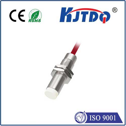
When selecting a limit switch for a PLC application, several factors must be considered. The mechanical configuration (lever, roller, etc.) must suit the motion of the target object. Environmental durability is critical; switches may need to be waterproof, dust-tight, or resistant to oils and chemicals. The electrical rating must match the PLC input module's requirements. Finally, the output type—typically a simple single-pole single-throw (SPST) contact—must be compatible.
In summary, the limit switch serves as the reliable "eyes" of a PLC system for physical position detection. Its robust, straightforward design delivers a clear digital signal that forms the basis for countless automated decisions within the PLC program. From ensuring precise repetitive motion to enforcing critical safety protocols, the combination of limit switches and PLCs forms a cornerstone of modern industrial automation. Understanding their interaction is essential for designing, maintaining, and optimizing automated systems for peak performance and safety.