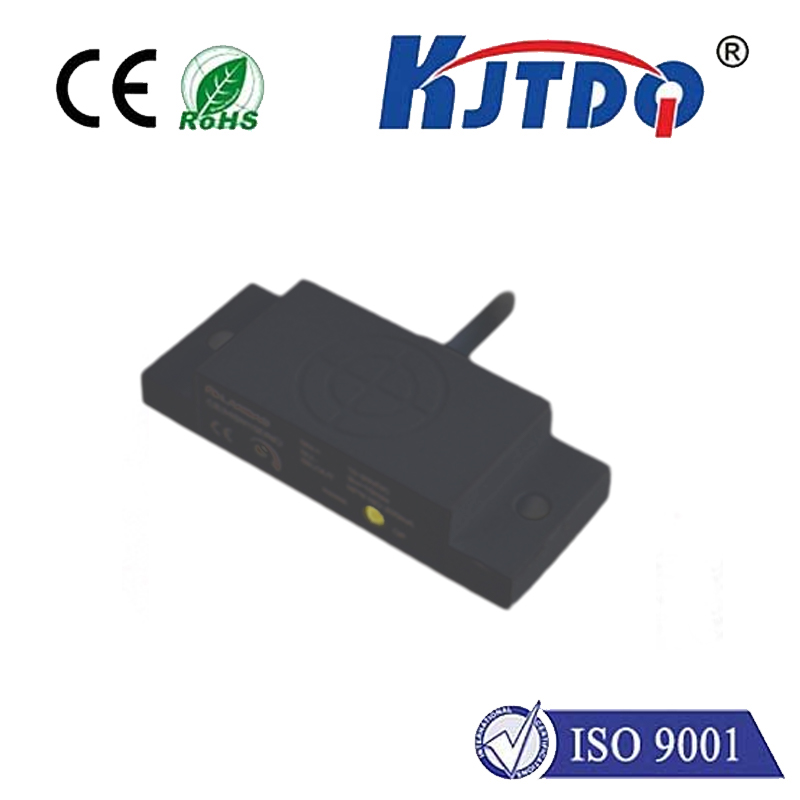
optical crankshaft position sensor
- time:2025-08-15 05:25:24
- Click:0
Optical Crankshaft Position Sensor: The Illuminating Heartbeat of Modern Engine Control
Modern engines are symphonies of precision. Every combustion event, every valve opening, every fuel injection pulse relies on knowing exactly where the crankshaft is positioned at any given microsecond. This critical role falls upon the often-unseen hero: the crankshaft position sensor (CKP). While magnetic (inductive) and Hall effect sensors have long been staples, optical crankshaft position sensors represent a sophisticated leap in accuracy and reliability, particularly vital for high-performance and demanding applications. Understanding their function reveals just how crucial they are to the seamless operation of your vehicle.
Beyond Magnets: The Optical Advantage
Traditional crankshaft position sensors rely on magnetic fields interacting with a reluctor wheel (toothed or notched disc) attached to the crankshaft. While effective, they can be susceptible to interference from stray magnetic fields, variations in air gap, and signal degradation at very low or very high speeds. Optical crankshaft position sensors, in contrast, harness the properties of light to perform the same fundamental task – detecting rotational position and speed – but with distinct advantages inherent to non-contact sensing via photons.
How Light Becomes Engine Data: The Core Principle
The operation of an optical crankshaft position sensor is elegant in its simplicity:

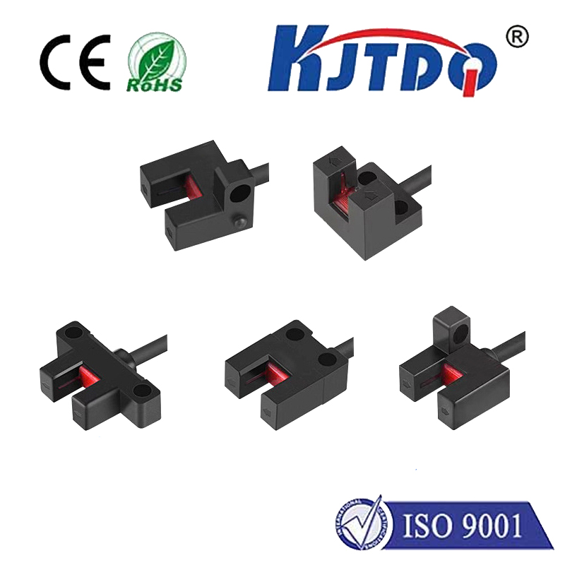
- The Light Source: An infrared Light Emitting Diode (LED) provides a constant beam of light.
- The Encoder Disc: Mounted directly on the crankshaft (or a shaft rotating in precise sync with it) is a specially designed disc. This disc has alternating sections that are transparent and opaque, effectively acting as a shutter. Sometimes, it features precisely positioned slits or holes instead of continuous segments.
- The Photodetector: Positioned opposite the LED, across the spinning encoder disc, sits a phototransistor or photodiode. This component acts as the “eye,” detecting the presence or absence of the LED’s light.
- Pulse Generation: As the crankshaft rotates, the encoder disc spins. When a transparent section or slit aligns between the LED and the photodetector, light passes through and strikes the detector, causing it to conduct electricity (generating a “high” signal). When an opaque section blocks the light, the detector stops conducting (generating a “low” signal). This rapid alternation between high and low states as the disc spins creates a precise digital pulse train.
- ECU Interpretation: The Engine Control Unit (ECU) constantly monitors this pulse train. It counts the pulses to determine engine RPM (revolutions per minute). Crucially, the ECU knows the exact pattern of the disc – for instance, which pulse corresponds to a specific cylinder reaching Top Dead Center (TDC). This allows it to pinpoint the absolute position of the crankshaft and, by extension, the pistons and valves, with exceptional accuracy. Timing is everything, and the optical CKP provides the clock.
Why Choose Light? Key Advantages of Optical CKP Sensors
The shift from magnetic fields to light offers several compelling benefits for engine management systems:
- Exceptional Precision & Resolution: Optical sensors can achieve incredibly fine resolution due to the ability to create numerous very fine slits or transitions on the encoder disc. This translates to extremely accurate position detection, vital for advanced ignition timing, variable valve timing (VVT/VCT), and direct fuel injection systems where timing windows are minuscule. Precision timing is non-negotiable for peak performance and efficiency.
- Immune to Magnetic Interference: Unlike magnetic sensors, optical types are completely unaffected by electromagnetic interference (EMI) from starter motors, alternators, ignition coils, or nearby electrical components. This ensures a clean, reliable signal under all operating conditions, crucial for robust engine performance and diagnostics.
- Superior Low-Speed Performance: Magnetic sensors require a minimum rotational speed to generate a usable signal (voltage). Optical sensors, detecting the presence or absence of light, function reliably right down to zero RPM (cranking speed) and even during very slow rotation. This provides the ECU with vital position data immediately during engine start-up for accurate fuel injection and spark timing on the very first stroke.
- Reduced Sensitivity to Air Gap: While precise installation is always recommended, optical sensors are generally less sensitive to variations in the gap between the sensor and the encoder disc compared to some magnetic sensors, offering more installation tolerance.
- Fast Response: Light travels fast! Optical sensors offer very rapid signal transition times, allowing the ECU to react almost instantaneously to changes in crankshaft position and speed.
Where Optics Shine: Ideal Applications
Given their advantages, optical crankshaft position sensors are commonly found in:
- High-Performance Engines: Where maximum power, efficiency, and precise control are paramount (e.g., motorsports, performance cars).
- Hybrid and Electric Vehicles: Providing critical crankshaft position data for seamless transitions between electric and internal combustion operation and for managing auxiliary functions driven by the engine.
- Diesel Engines: Especially those with sophisticated common-rail injection systems requiring pinpoint timing accuracy.
- Applications Demanding High Reliability in EMI Environments: Industrial engines, marine engines, or vehicles with complex electrical systems where signal integrity is critical.
- Situations Requiring Absolute Position at Zero RPM: Essential for accurate starting sequences.
Comparing Sensor Types
| Key Feature |
Optical CKP Sensor |
Magnetic (Inductive) CKP Sensor |
Hall Effect CKP Sensor |
| Sensing Principle |
Light (Infrared LED + Photodetector) |
Magnetic Flux Variation |
Magnetic Field Strength Change |
| Signal Output |
Precise Digital Pulse Train |
Analog Sine Wave (amplitude varies with RPM) |
Digital Square Wave |
| Zero RPM Signal? |
Yes (Detects position during cranking) |
No (Requires min. speed) |
Yes |
| EMI Sensitivity |
Immune |
Susceptible |
Generally Resistant |
| Air Gap Sensitivity |
Lower Sensitivity |
High Sensitivity |
Moderate Sensitivity |
| Resolution Accuracy |
Highest Potential |
Lower |
High |
| Typical Use Cases |
High-Performance, Hybrids, Critical EMI Env. |
Cost-effective Applications |
Widely Used, Reliable Digital Output |
The Critical Role in Engine Management
Regardless of type, the crankshaft position sensor is arguably the most important sensor in the engine. The ECU relies entirely on its input for:
- Calculating Engine Speed (RPM): Fundamental for all engine control strategies.
- Determining Ignition Timing: Precisely firing the spark plugs at the optimal moment for combustion.
- Controlling Fuel Injection: Determining precisely when to inject fuel and for how long (injector pulse width), synchronized with the intake stroke.
- Managing Variable Valve Timing (VVT/VCT): Adjusting camshaft timing based on crankshaft position and engine load/speed.
- Detecting Misfires: Identifying cylinders not contributing power by analyzing minute fluctuations in crankshaft speed detected by the sensor.
- Synchronizing Sequential Functions: Ensuring actions like sequential fuel injection or cylinder deactivation happen at precisely the right point in the combustion cycle.
Keeping the Light On: Reliability Considerations
While highly reliable, optical crankshaft position sensors share vulnerabilities common to engine bay components:
- Contamination: Dirt, oil, or debris accumulating on the encoder disc or the sensor’s optical window can block or scatter the light beam, leading to signal loss or corruption. Sealing is critical.
- Heat: Extreme engine bay temperatures, though the sensors are designed for it, can potentially affect the LED or photodetector over the very long term.
- **Physical


