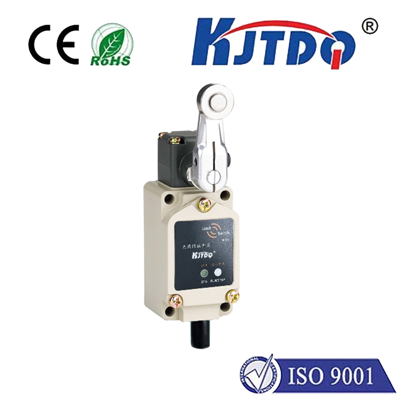
normally closed held open limit switch
- time:2025-08-06 12:23:41
- Click:0
Normally Closed Held Open Limit Switch: The Unsung Sentinel of Machine Safety
Imagine a heavy industrial press descending with immense force. Picture automated robotic arms moving rapidly within a cage. Visualize a passenger elevator ascending smoothly. Now, consider the absolute criticality of ensuring these operations only happen when it’s absolutely safe for personnel and equipment. Hidden within the control panels and guarding mechanisms of countless machines lies a crucial, often overlooked component: the Normally Closed (NC) Held Open Limit Switch. This specialized device isn’t just a switch; it’s a dedicated safety interlock, acting as a vigilant gatekeeper to prevent hazardous motion until specific safety conditions are unequivocally met.
Demystifying the “Normally Closed Held Open” Terminology
To grasp this switch’s unique role, let’s break down its defining characteristics:
- Normally Closed (NC): This describes the switch’s default electrical state when it’s completely at rest and not being physically activated. In an NC switch, the circuit is complete (closed) in its resting state. Electricity flows freely through it. This is the opposite of a Normally Open (NO) switch, where the circuit is open (broken) at rest.
- Held Open: This describes its operational state when performing its safety function. It means the switch is designed to be physically forced into its open position (breaking the circuit) by the presence of a safety guard, door, or other protective mechanism when that guard or door is properly in place and secured. The safety device “holds” the switch actuator depressed, keeping its contacts open.
The Crucial Safety Logic: Why NC and Held Open?

This combination creates an inherently fail-safe design for critical safety applications:
- Fail-Safe Principle: Safety circuits are often designed so that any failure (like a broken wire, loss of power, or a malfunctioning switch) defaults to the safest state – usually stopping the machine.
- The NC Held Open Mechanism at Work:
- Guard Closed & Secured: The physical guard presses the switch’s actuator, holding its contacts OPEN. This breaks the circuit running through the switch. This “open” signal is interpreted by the machine’s safety controller as “Guard is SAFE, machine may operate.”
- Guard Opened or Removed: When the guard is moved, it releases the switch actuator. Because the switch is Normally Closed, its contacts immediately snap back closed. This completes the circuit. The safety controller now detects a “closed” circuit, interpreting it as “Guard is OPEN, machine operation is UNSAFE.” It commands the machine to stop or prevents it from starting.
- Critical Advantage: If the wire connecting the switch snaps, or power is lost, the circuit is broken (it goes “open”), just as if the guard were open. The safety controller detects this loss or open circuit and triggers an immediate stop. This inherent design means a fault mimics the unsafe condition, forcing a shutdown – the essence of fail-safe operation. Using a Normally Open switch for this purpose would require closing the circuit to signal safety; a broken wire would falsely signal “safe” (no circuit change), creating a dangerous situation.
Where You’ll Find NC Held Open Limit Switches in Action
These specialized switches are the backbone of Physical Machine Guarding and Safety Interlocks:
- Machine Guards and Safety Doors: On CNC machines, presses, robots, assembly lines – anywhere access poses a danger. The guard must be securely closed, holding the NC switch open, before the hazardous motion can occur. Opening the guard instantly closes the NC contacts, stopping the machine.
- Access Hatches and Enclosures: Elevator pit access doors, electrical cabinet doors, or panels covering moving parts. Opening the hatch releases the switch, closing its contacts and cutting power to internal hazards.
- Safety Gates: Perimeter fencing around robots or automated guided vehicles (AGVs). Gates must be closed and secured (holding NC switch open) for the system to run. Opening a gate releases the switch and halts the nearby automation.
- Emergency Stop Monitoring (as part of a system): While dedicated E-Stop buttons are usually NC but work differently (closing on press), NC held open switches might be used on E-Stop pull-cord enclosures.
- Roller Coasters and Amusement Rides: Ensuring lap bars or restraints are securely locked (holding the switch open) before dispatch.
- Material Handling: Gates on conveyors or palletizers preventing access during operation.
Key Advantages: Safety, Reliability, Simplicity
- Robust Fail-Safety: As detailed, the design intrinsically fails towards the safe state.
- Clear Positive Safety Signal: The presence of the guard maintaining the “held open” state is the active requirement for enabling machine operation. Removal directly causes shutdown.
- Reliability: Simple mechanical design, often with heavy-duty housings and actuators built for industrial environments.
- Compliance: Helps meet stringent international safety standards (e.g., ISO 13849-1, IEC 62061, ANSI B11) governing machine guarding and safety-related control systems.
Maintenance Considerations for Optimal Safety
While inherently reliable, these critical safety components demand attention:
- Regular Inspection: Check for physical damage, secure mounting, and freedom of actuator movement. Ensure the guard positively actuates the switch every single time it closes.
- Testing: Periodically verify functionality as part of a Lockout-Tagout (LOTO) or safety procedure. Simulate opening the guard – the machine should stop instantly. Simulate a broken wire – the machine should also fail to start or stop immediately. Never bypass an interlock switch for operational convenience.
- Environmental Protection: Ensure the switch’s ingress protection (IP) rating is suitable for its environment (dust, moisture, chemicals, temperature).
- Wiring Integrity: Inspect wiring for damage or corrosion. Ensure connections are tight.
The Normally Closed Held Open Limit Switch is far more than a simple component. Its deliberate design leverages fundamental electrical principles to create a fundamental layer of personnel protection. By requiring the physical presence and correct positioning of a safety guard to maintain its specific “held open” state – which signals permission to operate – it forms a vital link in the safety chain. Understanding its normally closed nature and its held open operational requirement is key to appreciating its role as a guardian of life and limb in countless industrial settings, ensuring dangerous machines only move when it is genuinely safe to do so.