adding limit switches to 3018 cnc
- time:2025-08-01 11:30:14
- Click:0
Unlock Safety and Precision: Installing Limit Switches on Your 3018 CNC Machine
Every 3018 CNC machine owner knows the sickening crunch. That moment when the spindle carriage slams unexpectedly into its mechanical limits. It’s more than just a jarring noise; it’s potential damage to delicate leadscrews, stepper motors, critical alignment, or even your workpiece. While the 3018 CNC is a fantastic entry point into the world of computer-controlled machining, its lack of limit switches out-of-the-box is a significant omission. Adding these simple, inexpensive sensors is arguably one of the most impactful upgrades you can make for safety, machine longevity, and workflow efficiency. Let’s explore how to equip your 3018 with these essential digital guardians.
Why Limit Switches Are Non-Negotiable for Your 3018
Think of limit switches as your CNC’s emergency stop system and precise positioning guide rolled into one. They are electromechanical devices placed at the physical boundaries of each axis (X, Y, Z). When the machine’s carriage or spindle makes contact (or comes very close, depending on the switch type), it triggers an electrical signal sent directly to the CNC controller (like Grbl). This signal tells the controller:

- “STOP NOW - Boundary Reached!”: This is the primary safety function. It halts all motion instantly when an axis exceeds its intended travel, preventing hard crashes and mechanical damage. It protects your investment.
- “Home Position Found!” (When used as homing switches): Strategically placed at one end of each axis (often the “minimum” or “zero” end), they allow the machine to perform an automatic homing routine. When triggered during homing, the controller precisely knows where the machine head is located relative to a fixed datum point, ensuring consistent and accurate positioning for every job. Say goodbye to manual jogging to find zero!
- Enhanced Workflow: Automatic homing saves significant time before starting a job and allows for easy resumption after a pause or tool change. Some controllers also use them for soft limits, creating virtual boundaries within the physical travel.
Gathering Your Essential Components
Thankfully, adding limit switches to a 3018 CNC doesn’t require a fortune or an electrical engineering degree. Here’s what you typically need:
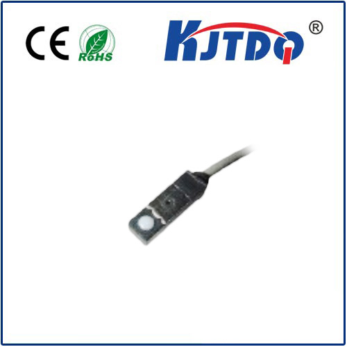
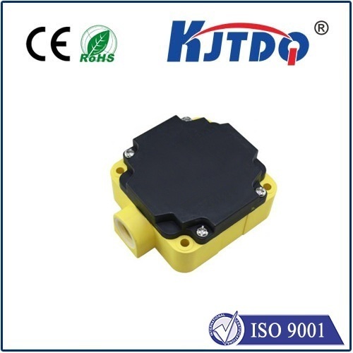
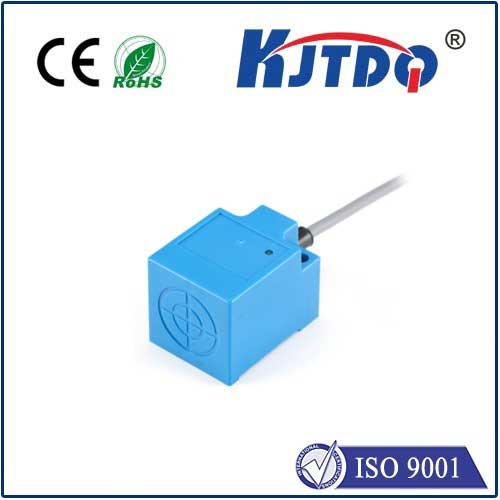
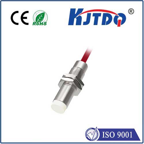
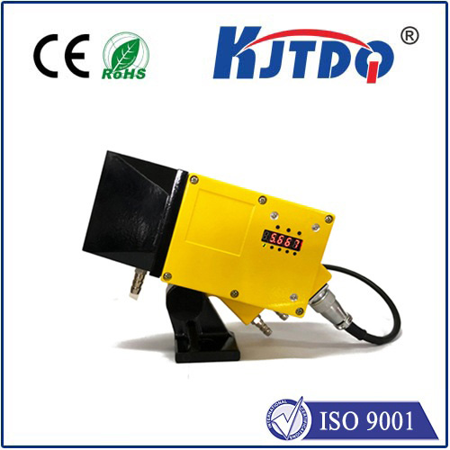
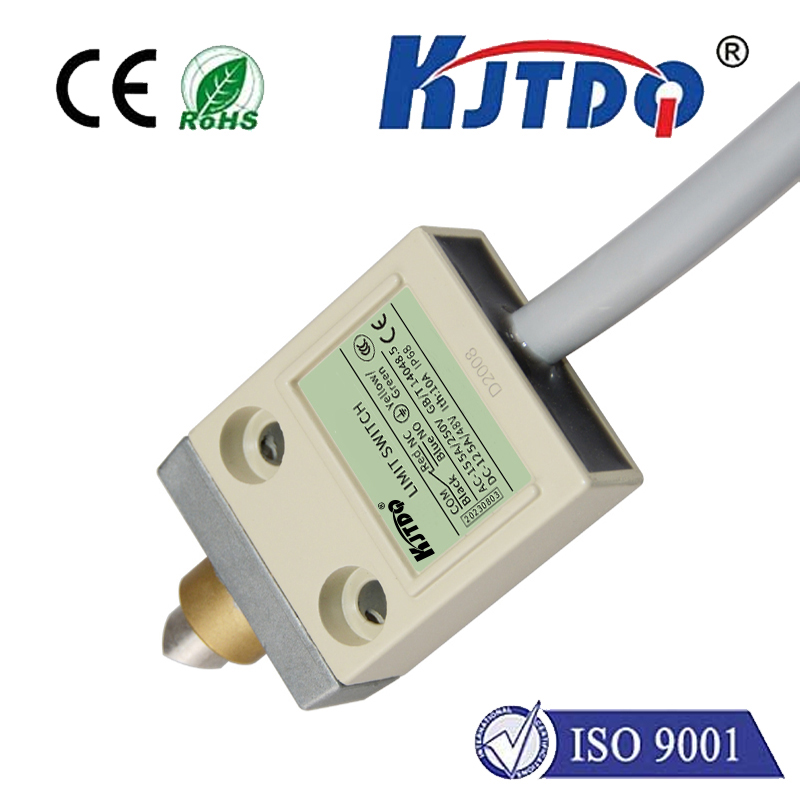
- Micro Limit Switches: Small, robust lever-arm switches (like the common KW12-3 style) are popular and cost-effective. Optical limit switches (using infrared beams) are contactless, avoid mechanical wear, and are highly reliable but slightly more expensive. Magnetic proximity sensors are another contactless option.
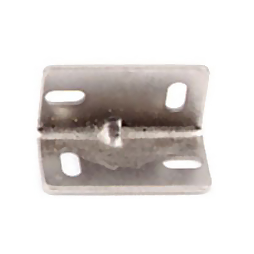
- Mounting Hardware: You’ll need small brackets, standoffs, screws, and perhaps printed or bent metal plates to securely position the switches at the ends of each axis. Think creatively – zip ties can be temporary solutions, but robust mounting is best.
- Wiring: Light gauge stranded wire (like 22-24 AWG), sufficient to connect each switch back to the control board. Shielded wire can sometimes help prevent electrical noise interference.
- Connectors: Often female Dupont connectors (2.54mm pitch) to plug into the control board headers. Crimping tools make this job cleaner.
- The Control Board: Ensure your specific 3018 CNC controller board has dedicated input pins for limit switches (X-, Y-, Z- for homing/min limits, and sometimes X+, Y+, Z+ for max limits). Most modern boards do (e.g., common clones based on Arduino Nano/Grbl). Consult your board’s documentation!
Step-by-Step Installation Guide
- Power Down Completely: Unplug the CNC machine from the wall. Safety first!
- Plan Mounting Positions: Identify where each switch will live. Common spots:
- X-axis: Mounted on the fixed gantry ends, triggering when the moving Y-carriage hits them.
- Y-axis: Mounted on the ends of the Y-carriage itself, triggering against fixed stops on the machine base.
- Z-axis: Mounted near the top of the Z-axis assembly, triggering when the spindle mount hits it.
- Crucially: Position the switches so they trigger just before the moving parts hit their absolute mechanical stops. Also, ensure the lever arm (if applicable) will reliably engage. Consider ease of access for wiring.
- Fabricate & Mount Brackets: Create or modify brackets to hold the switches securely at your planned locations. Ensure they won’t vibrate loose or interfere with machine motion. Mount the switches firmly.
- Route and Connect Wiring: Run wires from each switch back to the controller board location. Keep wires tidy and secured away from moving parts (spindle, belts) using cable ties or drag chains. Clearly label each wire (e.g., “X-Min”) at both ends!
- Wiring to the Controller: This is critical. Disconnect power again! Locate the dedicated limit switch input pins on your controller board. These are often labeled LIMIT X, LIMIT Y, LIMIT Z or similar. Grbl-based boards typically connect all limit switch signal wires together to one designated input pin (e.g., “X-Limit”), and connect all ground wires from the switches together to the board’s ground (GND). Double-check your specific board’s schematic! A common wiring scheme:
- One wire from every switch’s “Common” © or “Normally Open” (NO) terminal connects to the controller’s designated LIMIT pin.
- The other wire from every switch’s other terminal (usually the NO or C terminal) connects to the controller’s GND pin. This creates a circuit where triggering any switch connects LIMIT to GND.
- Secure Connections: Ensure all wires are firmly seated in connectors and screwed down securely on the switches. Loose connections cause frustrating intermittent faults.
Configuring Your CNC Controller (Grbl Focus)
The hardware install is only half the battle. You must tell the controller software that switches are present and how they should behave. Using software like Candle, UGS, or bCNC:
- Enable Homing ($22=1): This tells Grbl to use the limit switches for the homing cycle.
- Set Homing Directions ($23): This value (a bitmask) tells Grbl which direction to move for homing on each axis. For example,
$23=1 homes X in the negative direction, Y positive, Z negative. $23=2 homes all axes negative. Crucial: This must match your physical switch placement (usually min/negative ends).
- Set Homing Pull-off ($27): This is the distance Grbl backs off the switch after triggering it during homing to ensure it’s not held down. A value like 5.0 mm is common:
$27=5.0.
- Set Homing Feed Rates (\(20, \)21):
$20 sets