proximity sensor maximum sensing distance
- time:2025-07-19 08:52:13
- Click:0
Proximity Sensor Maximum Sensing Distance: Pushing the Limits of Detection
Ever carefully positioned a proximity sensor, only to find it stubbornly refuses to detect your target object at the expected range? You’re not alone. The maximum sensing distance – often listed as ‘Sn’ in datasheets – is a critical spec, but it’s frequently misunderstood. It represents the theoretical ideal range under perfect, laboratory-like conditions, not the guaranteed real-world performance. Understanding what truly defines this maximum distance, the factors that shrink it, and how different sensor technologies compare is essential for designing reliable, efficient automation systems. This is where many installations succeed or fail.
Decoding “Sn”: The Theoretical Maximum
At its core, the maximum sensing distance (Sn) is the absolute farthest distance at which a proximity sensor can reliably detect a standard target under strictly defined, optimal conditions. This “standard target” is crucial:
- Inductive Sensors: Typically specified using a square of mild steel (e.g., 1mm thick, side length equal to the sensor’s face diameter or the stated sensing distance, whichever is larger). Detection range drops significantly for non-ferrous metals.
- Capacitive Sensors: Usually specified with a grounded metal plate (e.g., similar size/thickness to inductive targets). Range is heavily influenced by the material’s dielectric constant (e.g., water and metals are detected farther than plastics).
- Photoelectric Sensors (Diffuse): Generally specified using white matte paper (e.g., Kodak 90% reflectivity) at a specific size. Shiny, dark, or small objects dramatically reduce range.
- Ultrasonic Sensors: Often stated for a large, flat, sound-reflective surface perpendicular to the beam.
Manufacturers rigorously test sensors against these standard targets under controlled environments – stable temperature, clean air (no dust, moisture, oil mist), ideal mounting, and optimal voltage supply. This Sn value is the benchmark, allowing apples-to-apples comparison between sensors of the same technology type. However, it is not a promise for your specific application.
Why Reality Falls Short: Factors That Reduce Achievable Range
Relying solely on the Sn value for system design is a recipe for frustration. Numerous factors conspire to shorten the effective sensing distance in the field:
- Target Properties:
- Size & Shape: Target smaller than the standard? Expect reduced range. Irregular shapes might reflect less effectively (light, sound) or distort electromagnetic fields (inductive/capacitive).
- Material: Inductive: Non-ferrous metals (aluminum, brass, copper) have significantly lower Sn compared to steel. Capacitive: Low-dielectric materials (plastics, wood) require closer proximity than water or metals. Photoelectric: Dark colors absorb light, reducing reflected signal; glossy surfaces cause specular reflection away from the sensor receiver. Ultrasonic: Soft or angled surfaces absorb or deflect sound waves.
- Surface: Dirt, rust, paint, or oxidation on the target can interfere with detection mechanisms.
- Environmental Conditions:
- Temperature: Extreme cold or heat can affect sensor electronics and emitter/receiver characteristics, shifting operating points.
- Contaminants: Dust, smoke, oil mist, steam, or heavy airborne particles can scatter light (photoelectric/IR), absorb sound (ultrasonic), or coat sensor faces, degrading performance.
- Electromagnetic Interference (EMI): Strong EMI sources near inductive or capacitive sensors can induce noise signals or mask the true sensing signal.
- Ambient Light: Intense ambient light (especially sunlight) can overwhelm photoelectric sensors, particularly diffuse types.
- Acoustic Noise: For ultrasonic sensors, loud background noise at similar frequencies can interfere with signal reception.
- Installation Factors:
- Mounting: Flush mounting is critical for shielded inductive/capacitive sensors to achieve Sn. Non-flush mounting or proximity to metal structures reduces range. Proper alignment is paramount for photoelectric and ultrasonic beam paths.
- Sensor Face Obstruction: Dirt, ice, paint, or physical damage on the sensor face drastically reduces effective range.
- Voltage Supply: Operation below the recommended voltage range can lower output power (emitter) or sensitivity (receiver).
- Adjacent Sensors: Mounting multiple sensors of the same type close together can cause mutual interference (cross-talk).
Technology Showdown: How Different Prox Sensors Compare for Range
Understanding the typical order of magnitude ranges achievable by different proximity sensor technologies helps narrow down choices:
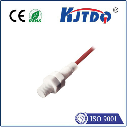
- Inductive Proximity Sensors: Range: Short. Typically millimeters to tens of millimeters (e.g., 1mm to 60mm is common). True Sn is highly material-dependent (steel vs. aluminum). Strengths: Excellent for metal detection, robust, immune to non-metallic contaminants. Weakness: Very limited range, metal-only.
- Capacitive Proximity Sensors: Range: Short to Medium. Can range from a few millimeters up to around 40-50mm for some models. Highly dependent on the material’s dielectric constant and grounding. Strengths: Detects virtually any material (liquids, powders, plastics, metals), good for level sensing. Weakness: Susceptible to moisture/humidity and environmental buildup on the face; requires calibration.
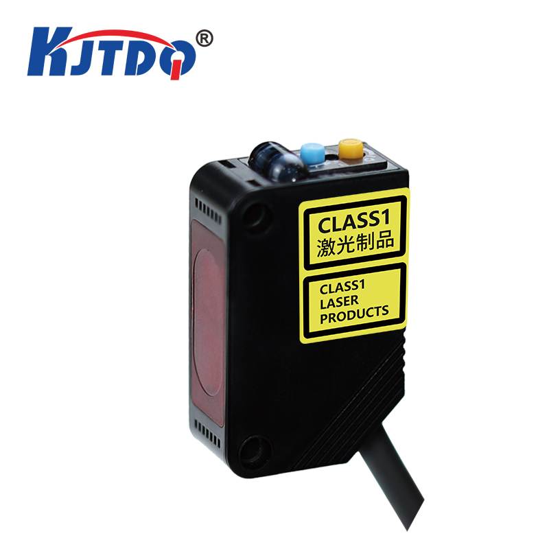
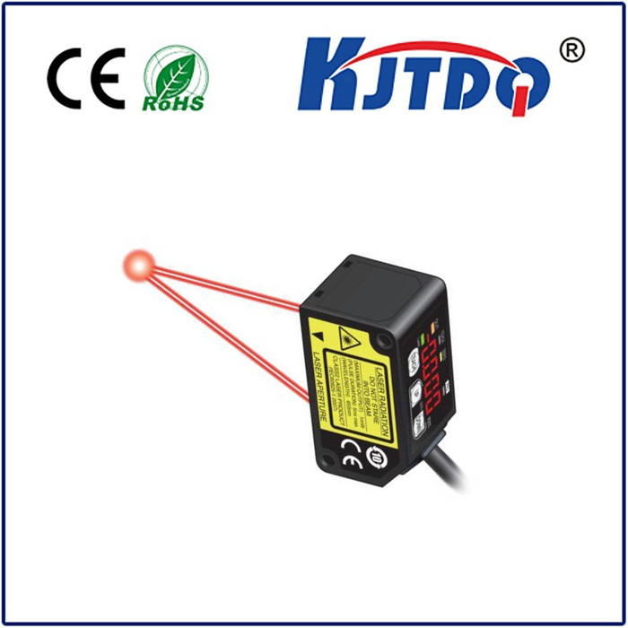
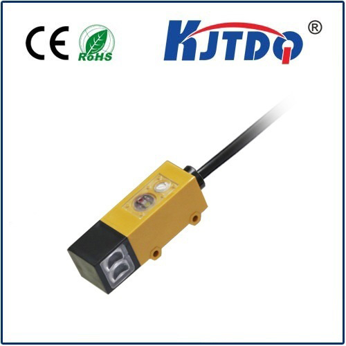
- Photoelectric Sensors - Diffuse (Reflective): Range: Short to Medium. Varies wildly based on model and technique (standard diffuse, background suppression - BGS, foreground suppression - FGS). Can be a few centimeters up to 1-2 meters for powerful models against ideal targets. Color and surface finish drastically affect range. Strengths: Versatile, detects most non-metallic objects well, reasonable range. Weakness: Performance heavily degraded by target color/surface, ambient light, and airborne contaminants.
- Photoelectric Sensors - Retroreflective: Range: Medium to Long. Typically 100s of millimeters up to 5-15 meters or more. Utilizes a reflector for better signal return. Less affected by target color than diffuse, but dust/dirt on reflector or lens is problematic. Strengths: Good long-range capability, more reliable on varied surfaces than diffuse.
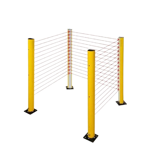
- Photoelectric Sensors - Through-Beam (Emitter/Receiver): Range: Long to Very Long. The king of range. Easily achieves meters (10m, 20m, 50m, even 100m+ models exist). The beam travels directly from emitter to receiver. Performance least affected by target color/surface or ambient light (compared to other photoelectric modes). Strengths: Maximum range & reliability for photoelectrics, excellent for large area monitoring. Weakness: Requires wiring and mounting at two separate points (emitter and receiver), alignment critical.
- Ultrasonic Sensors: Range: Medium to Very Long. Commonly spans from centimeters up to several meters (e.g., 300mm to 6-8m), with specialized long-range models exceeding 10m. Effective on most solid/liquid surfaces regardless of color or material (though soft/absorbent surfaces reduce range). Strengths: Excellent range, material independent, detects clear objects, good in dusty/foggy environments. Weakness: Slower response time than most prox sensors, temperature sensitive (requires compensation), can suffer from acoustic noise/background echoes.
Optimizing for Maximum Reliable Range: Practical Strategies
Achieving performance as close to the Sn value as possible requires deliberate design and maintenance:
- Know Thy Target: Precisely identify material, size, shape, and surface condition. Choose the sensor technology best suited to these properties. Don’t expect capacitive Sn when detecting plastic if the datasheet Sn was defined with metal.
- Respect the Environment: Analyze temperature extremes, potential contaminants (dust, oil, steam), ambient light sources, EMI sources, and background noise. Select sensors rated to withstand these conditions and employ protective measures (housings, air curtains, filters).
- Installation Perfection: Follow manufacturer mounting guidelines meticulously. Ensure flush mounting where required. Achieve precise alignment for beam-based sensors. Maintain adequate clearance between adjacent sensors. Keep sensor faces clean and unobstruct


