proximity sensor for rpm measurement
- time:2025-06-24 02:43:36
- Click:0
Unseen Spins, Precise Reads: Proximity Sensors Revolutionize RPM Measurement
For engineers, maintenance technicians, and automation specialists, knowing how fast a shaft or wheel is spinning isn’t just data – it’s critical intelligence. Rotational speed (RPM) is the lifeblood signature of countless machines, from humble conveyor belts to high-turbine jet engines. Monitoring it ensures optimal performance, prevents catastrophic failures, and enables predictive maintenance. But how do you accurately measure something spinning at high speeds, often in harsh environments, without physically touching it and disrupting its operation? This is where the proximity sensor steps into the spotlight as an indispensable tool for non-contact RPM measurement.
Traditionally, methods like mechanical tachometers required physical contact, introducing friction and potential wear. Optical encoders offer precision but can be susceptible to dirt, dust, and oil – common adversaries in industrial settings. Stroboscopic lights are useful but impractical for continuous monitoring. The need for a robust, reliable, and non-intrusive solution is paramount. Proximity sensors, particularly inductive proximity sensors, excel in this demanding arena, offering a compelling blend of durability, accuracy, and ease of integration.
The Core Principle: Sensing Without Touching
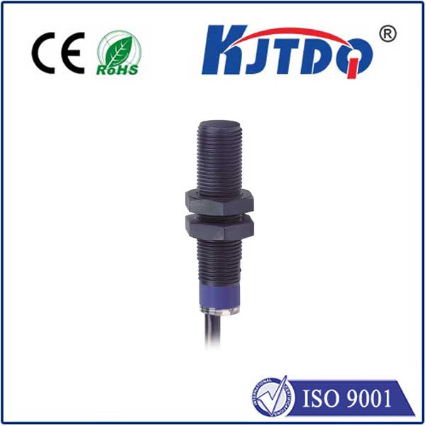
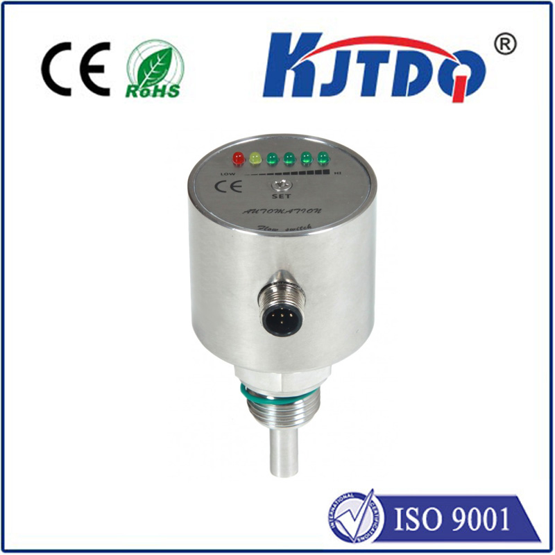
At its heart, a proximity sensor detects the presence or absence of a target object without physical contact. For RPM measurement, the target is typically a feature on the rotating component – a gear tooth, a keyway slot, a bolt head, or even a specially mounted metal tab or flag. The most common type used is the inductive proximity sensor.

Here’s the mechanism in action:
- The Sensor’s Field: The sensor head generates a high-frequency electromagnetic field.
- Target Interaction: As a metallic target (like a gear tooth) enters this field, it induces small eddy currents on the target’s surface.
- Field Disturbance: These eddy currents draw energy from the sensor’s oscillator circuit, causing a measurable change (usually a damping effect).
- Signal Output: The sensor’s internal circuit detects this change and triggers a clean, digital output signal – typically a switch from high to low voltage (or vice versa) – every time a target feature passes by.
- Counting Pulses: This digital pulse train is then fed into a counter, timer, or Programmable Logic Controller (PLC).
- RPM Calculation: The receiving device counts the number of pulses received over a precisely known time interval. Since each pulse represents one target pass (one revolution per target, or more commonly, multiple targets per revolution), the rotational speed in Revolutions Per Minute (RPM) is readily calculated using the formula:
RPM = (Number of Pulses / Time Period in minutes) / Number of Targets Per Revolution (PPR)- Or more practically for short time intervals:
RPM = (Number of Pulses * 60) / (Time Period in seconds * PPR)
Why Inductive Proximity Sensors Shine for RPM
The widespread adoption of inductive proximity sensors for rotational speed monitoring is no accident. They offer several distinct advantages:
- Ruggedness and Reliability: Housed in robust metal or polymer casings, these sensors withstand shock, vibration, extreme temperatures, and common industrial contaminants like dust, oil, grease, and moisture (often rated IP67 or higher). Their solid-state design has no moving parts to wear out.
- True Non-Contact Operation: There is zero physical wear on either the sensor or the target, leading to exceptionally long service life and consistent accuracy.
- Immunity to Contaminants: Unlike optical sensors, they are largely unaffected by dirt, dust, smoke, oil mist, or other opaque substances that would obscure a light beam. This makes them ideal for dirty environments like mining, heavy manufacturing, or pulp and paper plants.
- High-Speed Capability: Modern inductive sensors can detect targets passing at very high frequencies, easily handling rotational speeds encountered in motors, turbines, gearboxes, and drives, often exceeding tens of thousands of RPM.
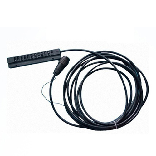
- Simple Installation and Integration: Mounting typically involves securing the sensor at an appropriate sensing distance (usually within millimeters) from the target path. Their standard PNP or NPN output interfaces seamlessly with industrial control systems, counters, and data loggers.
- Cost-Effectiveness: They offer a high-performance, durable solution at a relatively low cost compared to more complex optical encoder systems.
Implementing Proximity Sensors for RPM: Key Considerations
While powerful, successful implementation requires attention to detail:
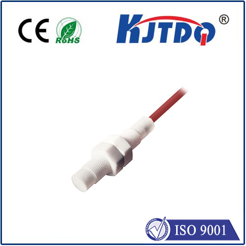
- Sensor Selection: Choose the right sensor type (inductive is most common, but capacitive can be used for non-metallic targets). Consider factors like sensing distance, operating temperature, supply voltage, output type, and housing material. Ensure the sensor’s specified switching frequency exceeds the maximum expected pulse frequency at the target RPM.
- Target Design: The target feature (tooth, slot, flag) must be metallic for inductive sensors. Its size, shape, and material significantly impact sensing reliability. Consistency in target features is crucial for accurate pulse counting. The number of targets per revolution (PPR) is fundamental to the RPM calculation.
- Mounting Position: Sensor position relative to the target path is critical. Axial mounting (sensing the end of a shaft with a target) or radial mounting (sensing the side of a gear or wheel) are common. Ensure stable mounting to prevent vibration-induced errors.
- Air Gap: Maintain the sensor’s specified nominal sensing distance. Too large a gap causes missed detections; too small risks physical damage. Account for potential shaft runout or vibration.
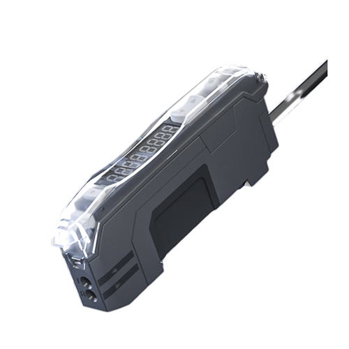
- Signal Processing: The digital pulse output needs reliable counting and timing. PLCs are ubiquitous for this, but dedicated tachometers, frequency counters, or data acquisition systems can also be used. Ensure the processing device can handle the maximum pulse frequency.
- Electrical Noise: In industrial environments, electrical noise can interfere with sensor signals. Use shielded cables, proper grounding techniques, and physically separate sensor cables from power lines.
Beyond Inductive: Alternatives for Specific Needs
While inductive sensors dominate, other proximity technologies fill specific niches:
- Capacitive Proximity Sensors: Can detect non-metallic targets (plastic gears, rubber belts, liquid levels) but may be influenced by humidity or coating buildup, and generally have shorter sensing ranges.
- Magnetic (Hall Effect) Sensors: Detect the presence of magnetic fields. Ideal if a permanent magnet can be embedded in or attached to the rotating shaft. Highly immune to non-ferrous contaminants but require a magnetic target.
- Photoelectric Sensors: Excellent for very high precision or very high speeds where non-metallic targets are involved, but their performance degrades significantly in dirty or foggy conditions compared to inductive sensors.
Proven in the Field: Real-World Impact
The application of proximity sensors for RPM measurement is vast. They are the silent guardians ensuring:
- Motor Overspeed Protection: Preventing catastrophic failure in pumps, fans, and compressors by triggering shutdowns if RPM exceeds safe limits.
- Conveyor Belt Speed Control: Providing feedback for precise speed regulation in packaging, sorting, and material handling lines.
- Gearbox and Transmission Monitoring: Detecting changes in output shaft speed that indicate wear, slipp