proximity sensor proteus
- time:2025-06-24 00:15:25
- Click:0
Mastering Proximity Sensor Simulation in Proteus Design Suite
Simulate, Test, Perfect: Your Guide to Proximity Sensor Integration Using Proteus
Bringing a hardware design to life often feels like navigating a maze blindfolded. Physical prototyping consumes precious time and resources, especially when integrating sensitive components like proximity sensors. Imagine the frustration of soldering boards only to discover a critical flaw in your sensor circuit. This is where the power of Proton IDE Proteus simulation becomes indispensable. By leveraging tools like Proteus, electronics designers and hobbyists can simulate proximity sensors virtually, rigorously testing interactions and logic before soldering a single component, saving cost, time, and immense frustration.
Why Simulate Proximity Sensors in Proteus?

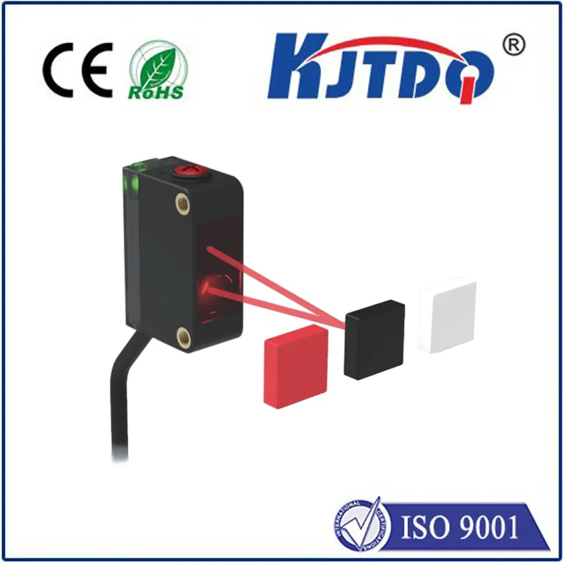
Proximity sensors are ubiquitous in modern electronics, detecting nearby objects without physical contact. You’ll find them in smartphones (screen dimming during calls), industrial automation (object detection on assembly lines), robotics (collision avoidance), and countless consumer devices. Implementing them correctly requires precise tuning of detection ranges, signal conditioning, and integration with microcontrollers.
Building and debugging these circuits physically is inherently iterative and often tedious. Proteus offers a compelling alternative:
- Cost Efficiency: Eliminate expensive component wastage and PCB re-spins caused by design errors found late in the physical build.
- Rapid Prototyping: Test multiple sensor types (IR, Ultrasonic, Capacitive, Inductive) and circuit configurations within minutes.
- Deep Insight: Probe voltage levels, current flows, and microcontroller responses at any point in the circuit, revealing issues invisible on a physical board.
- Risk Mitigation: Safely test edge cases and fault conditions that might be risky or damaging to test on real hardware.
Key Proteus Components for Proximity Sensor Simulation
Proteus boasts an extensive library of virtual components essential for sensor circuit design:
- Sensor Models: Look for models like
IR_SENSOR, ULTRASONIC_SENSOR, or specific part numbers (e.g., models mimicking Sharp GP2Y0A series IR sensors). These can often be found in the official Proteus libraries or reputable third-party sources like The Engineering Projects.
- Microcontrollers (MCUs): The heart of your design. Proteus supports a vast range (PIC, AVR, ARM Cortex-M, 8051, Arduino). Simulate your code interacting directly with the simulated sensor signal.
- Voltage Comparators (e.g., LM393, LM339): Essential for converting the analog output of many proximity sensors into a clean digital signal for the MCU. Proper biasing of the comparator’s reference voltage is critical.
- Operational Amplifiers (Op-Amps): Used for amplifying weak sensor signals or implementing specific signal conditioning filters. Models like LM358 are readily available.
- Resistors, Capacitors, Diodes: Fundamental passive components for biasing sensors, setting comparator thresholds, filtering noise, and protecting circuits.
- Voltage Sources & Grounds: Provide stable power rails (
VCC, GND) – always double-check your power connections!
- Virtual Instruments: Voltmeters, ammeters, oscilloscopes (especially powerful), logic analyzers – vital for debugging signal integrity and timing.
- Animated Objects: Simple colored blocks or shapes that you can use to simulate “objects” moving in and out of the sensor’s detection field during simulation.
Step-by-Step: Simulating an IR Proximity Sensor in Proteus
Let’s walk through a common scenario: simulating an IR reflective proximity sensor interfaced with a microcontroller.
- Schematic Design:
- Place your chosen IR sensor model (e.g., search for
IR_SENSOR or a specific part model) on the schematic.
- Place your target microcontroller (e.g., Arduino Uno, PIC16F877A, STM32F103C8 “Blue Pill”).
- Add the necessary comparator (like
LM393). Connect the sensor’s analog output to the comparator’s non-inverting input (+).
- Set the detection threshold. Connect a voltage divider (using resistors
R1, R2) between VCC and GND. Connect the divider’s midpoint to the comparator’s inverting input (-). Adjusting R1/R2 values effectively changes the detection distance in simulation.
- Add a pull-up resistor
(e.g., 10KΩ) to the comparator’s output pin (often labeled OUT). Connect this output to one of your MCU’s digital input pins.
- Wire up
VCC and GND connections to all active components. Missing power is the #1 cause of simulation failure!
- Optionally, place an LED and series resistor connected to an MCU output pin to visually indicate detection.
- Firmware Coding:
- Write or adapt your microcontroller code (in C, C++, Arduino IDE, etc.) to read the state of the digital input pin connected to the comparator output.
- Program the logic: Turn on the indicator LED when the pin goes
HIGH (or LOW, depending on your comparator wiring and sensor logic), signifying object detection.
- Compile the code to generate a
.hex file (or similar format your MCU model requires).
- Proteus Simulation Setup:
- Double-click the MCU component on the schematic. Navigate to the “Program File” property and load your compiled
.hex file. Set the correct clock frequency.
- Place animated objects near the sensor symbol or use the mouse pointer itself to trigger the sensor during simulation.
- Running & Analyzing the Simulation:
- Click the “Play” button (▶) to start the simulation.
- Move your animated object close to the IR sensor symbol. Observe:
- Does the comparator output change state?
- Does the MCU detect this change?
- Does the indicator LED turn on/off correctly?
- Use the oscilloscope: Probe the sensor’s analog output to see the raw signal change as an object approaches. Probe the comparator’s input (
+ and -) and output to ensure it switches correctly when the analog signal crosses the threshold you set.
- Debug: If something doesn’t work:
- Check all wiring and
VCC/GND connections meticulously.
- Verify the comparator’s reference voltage is correctly set and stable.
- Use the voltmeter to check power levels.
- Ensure the MCU clock frequency setting matches your code assumptions.
- Double-check the logic in your firmware (e.g., Is it looking for a
HIGH when you wired the comparator for active-LOW?).
Best Practices for Effective Proteus Proximity Sensor Simulation
- Model Fidelity Matters: Understand the limitations of the specific sensor model you are using in Proteus. Does it accurately reflect the real sensor’s voltage output range and response curve? If high precision is critical, you might need to model the sensor behavior yourself using voltage-controlled sources or complex scripts.
- Simulate Noise: Introduce realistic electrical noise sources to test your circuit’s robustness. Add small signal generators or voltage sources with noise waveforms to simulate interference on power lines or sensor cables.
- Test Boundary Conditions: What happens when an object is just at the edge of detection? Does the output chatter? Test these scenarios to ensure stable operation. Adjust hysteresis on the comparator if necessary.
- Leverage Virtual Instruments: The oscilloscope is your best friend. Use it constantly to visualize signal integrity and timing issues that would be impossible to see otherwise. The logic analyzer is