check

check

check

check
Integrating a limit switch with a stepper motor on an Arduino platform is a fundamental technique for adding precision and safety to automated projects. Whether you're building a CNC machine, a 3D printer, or an automated camera slider, understanding this combination is crucial for defining physical boundaries and establishing a reliable home position. This guide walks through the practical steps, component selection, and code logic to achieve robust control.
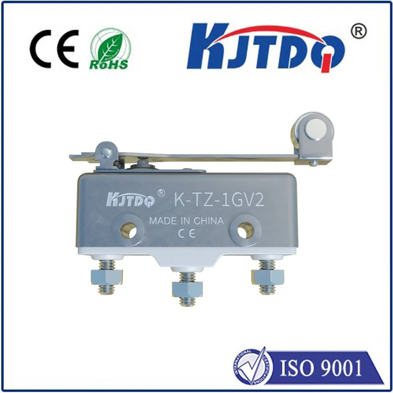
A limit switch is a simple electromechanical device that acts as a digital sensor. It typically has a lever or plunger that, when pressed, changes its electrical state. In the context of a stepper motor, its primary role is to detect the end of travel in a linear or rotational motion system. This prevents the motor from straining against mechanical stops, which can cause skipped steps, motor overheating, or damage to the drive mechanics. By connecting a limit switch to an Arduino's digital input pin, you can program the motor to stop or reverse direction upon activation.
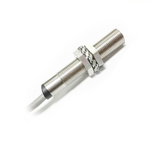
For this setup, you will need an Arduino board (Uno or Nano are excellent choices), a stepper motor (like a NEMA 17), a compatible driver module (such as the A4988 or DRV8825), a limit switch (normally open type is common), jumper wires, and an external power supply for the motor. The stepper driver is essential as the Arduino's pins cannot supply the necessary current to drive the motor directly. Connect the driver to the Arduino: typically, theSTEP andDIR pins connect to any digital pins, and theENABLE pin can be connected for power management. The motor coils connect to the driver's outputs. Power the driver's logic side from the Arduino's 5V and the motor power from your external supply, ensuring the voltage matches your motor's specifications.
Wiring the limit switch is straightforward. One terminal of the switch connects to the Arduino's ground. The other terminal connects to a chosen digital input pin (e.g., pin 2). For reliable reading, you should use the Arduino's internal pull-up resistor. This is done in software by setting the pin mode toINPUT_PULLUP. In this configuration, the pin readsHIGH when the switch is open (not pressed). When the switch is pressed and closes the circuit to ground, the pin readsLOW. This "active-low" configuration is preferred as it is less susceptible to electrical noise.
The core logic of the Arduino sketch involves continuously monitoring the limit switch state while controlling the motor. TheStepper library or the more preciseAccelStepper library is highly recommended. The basic algorithm is a loop that checks if the limit switch pin isLOW. If it is, the program must immediately stop the motor or execute a homing sequence. A simple movement sketch might first command the motor to move in one direction until the limit switch is triggered. Upon triggering, the motor stops, and its position can be reset to zero, establishing a known reference point. This homing routine is the first step in any precise positioning system.
Consider this practical code structure. After including theAccelStepper library and defining the connections, in thesetup() function, set the limit switch pin asINPUT_PULLUP. In theloop(), a command likestepper.moveTo(10000) tells the motor to move. However, inside the main control loop, a constant checkif(digitalRead(limitSwitchPin) == LOW) is performed. When true, the program callsstepper.stop() andstepper.setCurrentPosition(0) to home the system. It's vital to include a small debounce delay after detecting the switch to avoid false triggers from mechanical bouncing.
Beyond basic homing, advanced implementations use two limit switches—one for each end of travel—to define a safe operating range. The motor can be programmed to move between these two limits autonomously. Furthermore, you can implement a "search for home" routine on startup, where the motor slowly moves towards a limit switch to find its zero position before beginning any operation. This ensures repeatability every time the system is powered on. Always ensure your mechanical mounting is secure; the switch must be positioned so that the moving part activates it reliably before hitting a hard stop. Adjust the sensitivity if using a lever-arm switch.
Troubleshooting common issues is part of the process. If the motor does not stop at the switch, verify your wiring and that the pin readsLOW when pressed using the Serial Monitor. Ensure the motor power supply is adequate. If the motor vibrates or stalls, adjust the current limit on the driver module. Remember, the limit switch provides a physical reference, but the accuracy of positions after homing depends entirely on the stepper motor not losing steps. Using microstepping on the driver can provide smoother motion.
Mastering the use of a limit switch with a stepper motor unlocks a new level of reliability for Arduino-based automation. It transforms an open-loop system into one with a defined starting point, preventing cumulative errors and mechanical failures. By following the wiring practices and code logic outlined here, you can confidently add this essential feature to your next robotics or precision motion control project, ensuring it operates safely within its intended physical boundaries.