check

check

check

check
check
check
check
check

check

check
For anyone diving into the world of electronics prototyping, especially with microcontrollers like Arduino or Raspberry Pi, understanding how to properly integrate components is crucial. Among these components, the humble limit switch plays a vital role in countless projects, from 3D printers and CNC machines to interactive art installations and automated home systems. This guide focuses on a practical and visual approach to incorporating limit switches into your designs using Fritzing, a popular open-source tool for creating clear electronic schematics and PCB layouts.
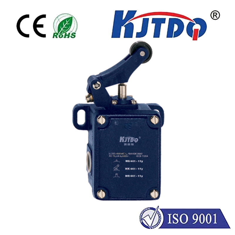
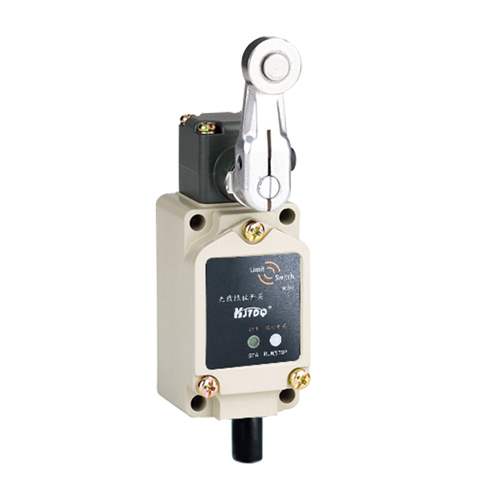
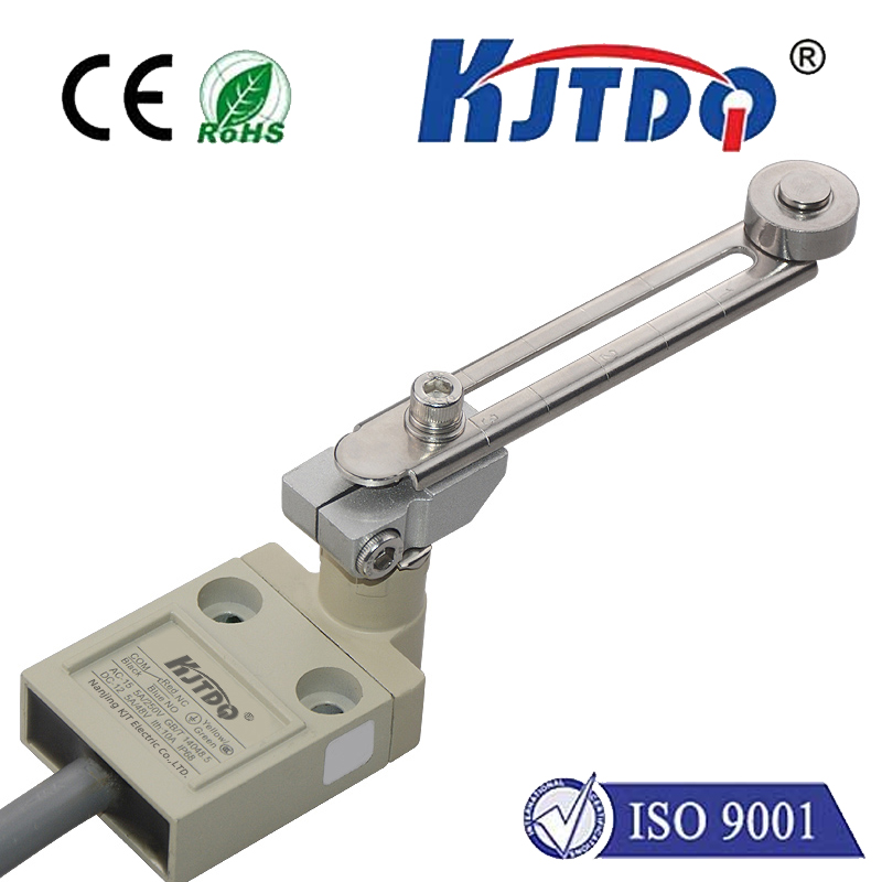
A limit switch is a simple electromechanical device. It typically consists of an actuator (a lever, button, or roller) linked to a set of internal contacts. When an object physically contacts the actuator, it triggers the switch to change state—either opening or closing an electrical circuit. This makes it perfect for detecting the presence, absence, or position of an object. Common applications include defining the home position on a moving axis, preventing over-travel, counting objects on a conveyor, or creating a safety interlock. Understanding its basic operation—normally open (NO) or normally closed (NC) configurations—is the first step before any software modeling.
This is where Fritzing becomes an invaluable ally. Fritzing bridges the gap between the physical breadboard and the abstract circuit diagram. Its intuitive, breadboard-centric view allows users to drag and drop components and connect them with virtual wires, closely mimicking the hands-on prototyping process. For a maker documenting a project or an educator preparing instructional materials, the clarity Fritzing provides is unmatched. It helps visualize the entire circuit, including the microcontroller, power connections, and peripheral components like our limit switch, before a single real wire is bent.
So, how do you create a limit switch circuit in Fritzing? The process is straightforward. First, open Fritzing and navigate to the "Core" parts bin. You might find a generic switch component. For better accuracy, the Fritzing community has created and shared many custom parts. You can often find a more realistic limit switch part by searching online repositories or the "Contributor" parts within Fritzing. Once you have your component, drag it onto the breadboard view. A typical wiring for an Arduino project involves connecting one terminal of the switch (for a NO configuration) to a digital input pin (e.g., Pin 2). The other terminal connects to the ground (GND). To ensure a stable reading when the switch is open, a pull-up resistor is essential. You can use the Arduino's internal pull-up resistor by setting the pin mode toINPUT_PULLUP in your code, which simplifies the physical wiring. In Fritzing, you would simply show a wire from the switch's input pin connection to the digital pin and another wire from the same junction to GND, acknowledging the internal resistor's role.
The real power of Fritzing is realized in its multiple views. The *Breadboard View* gives you the prototyping layout. The *Schematic View* automatically generates a standardized electrical diagram from your breadboard, perfect for technical documentation. The *PCB View* allows you to design a custom printed circuit board if you plan to move your prototype to a permanent form. For a limit switch circuit, ensuring clean connections in the schematic and considering trace routing for noise immunity in the PCB view are good practices. Always double-check that your Fritzing diagram matches your intended physical wiring and code logic. A common pitfall is misrepresenting the switch type (NO vs. NC), which would lead to inverted logic in the controlling software.
Beyond basic connection, consider practical integration tips. Limit switches are often used in pairs or multiples for end-of-travel detection on both ends of a linear motion. Model this in Fritzing by placing multiple switch components. Show how they share common ground connections but report to separate digital pins. Furthermore, consider adding indicator LEDs to your Fritzing diagram to visually represent the switch's state, which is excellent for educational purposes. When writing the accompanying code (which you can annotate in your project documentation), remember to implement debouncing—a software technique to ignore mechanical chatter from the switch contacts. While Fritzing doesn't simulate this, your diagram is the foundation for writing correct code.
Mastering the use of Fritzing for components like limit switches empowers you to plan better, document thoroughly, and communicate your electronic ideas effectively. It turns a simple switching mechanism into a clearly understood part of a larger system. Start by recreating a basic limit switch circuit, experiment with different configurations, and leverage the community parts to make your diagrams as accurate as possible. This disciplined approach in the virtual world saves time, prevents errors, and leads to more successful and professional-looking projects in the real world.