check

check

check

check
check
check
check
check

check

check
Integrating a limit switch with a stepper motor and an Arduino board is a fundamental skill for building precise and reliable automated systems. This setup is crucial in applications like 3D printers, CNC machines, or any project where controlling the range of motion is essential to prevent damage and ensure repeatability. The limit switch acts as a reliable sensor, providing a definitive physical reference point, while the stepper motor offers accurate positional control. The Arduino serves as the perfect brain to orchestrate their interaction.
The core principle is straightforward. A mechanical limit switch is typically a normally-open (NO) or normally-closed (NC) switch. When an actuator or moving part presses the switch's lever, it changes its electrical state. For safety in homing sequences, a normally-closed configuration is often preferred because a broken wire simulates the "pressed" state, triggering a safe stop. This signal is read by the Arduino via a digital input pin. The stepper motor, driven by a dedicated driver module like the A4988 or DRV8825, receives step and direction signals from the Arduino.
A typical wiring setup involves connecting the limit switch between a digital pin (e.g., pin 2) and ground, using the Arduino's internal pull-up resistor. The stepper driver is connected to the Arduino's digital pins for STEP and DIRECTION, and to a suitable power supply for the motor. The real magic happens in the code. The Arduino sketch continuously monitors the state of the limit switch pin. When the switch is triggered (pin goes LOW in a pull-up, NC configuration), the program must immediately halt the stepper motor's movement in that direction.
A basic implementation involves a simpledigitalRead() inside theloop(). However, for more robust performance, especially during fast homing routines, using hardware interrupts is highly recommended. By attaching an interrupt to the limit switch pin, the Arduino can react instantly to the switch being pressed, regardless of what else the main code is doing. The Interrupt Service Routine (ISR) can set a flag or directly disable the stepper driver to stop motion immediately.
Beyond simple stopping, a common application is the homing sequence. Upon startup, a machine often doesn't know its position. The program commands the stepper motor to move slowly in one direction until the limit switch is activated. This moment defines the "home" or zero position. Once detected, the motor stops, and the Arduino's internal position counter is reset. From this known reference, the motor can then move accurately to any other position within its travel limits.
When writing the code, debouncing the switch is a critical consideration. Mechanical switches can produce multiple rapid on-off signals (bouncing) when pressed, which the Arduino might read as multiple triggers. Implementing a simple software debounce delay of 10-50 milliseconds after the first detection ensures a single, clean signal. Furthermore, logic should be included to prevent the motor from continuing to push against a triggered switch, which wastes power and could cause damage.
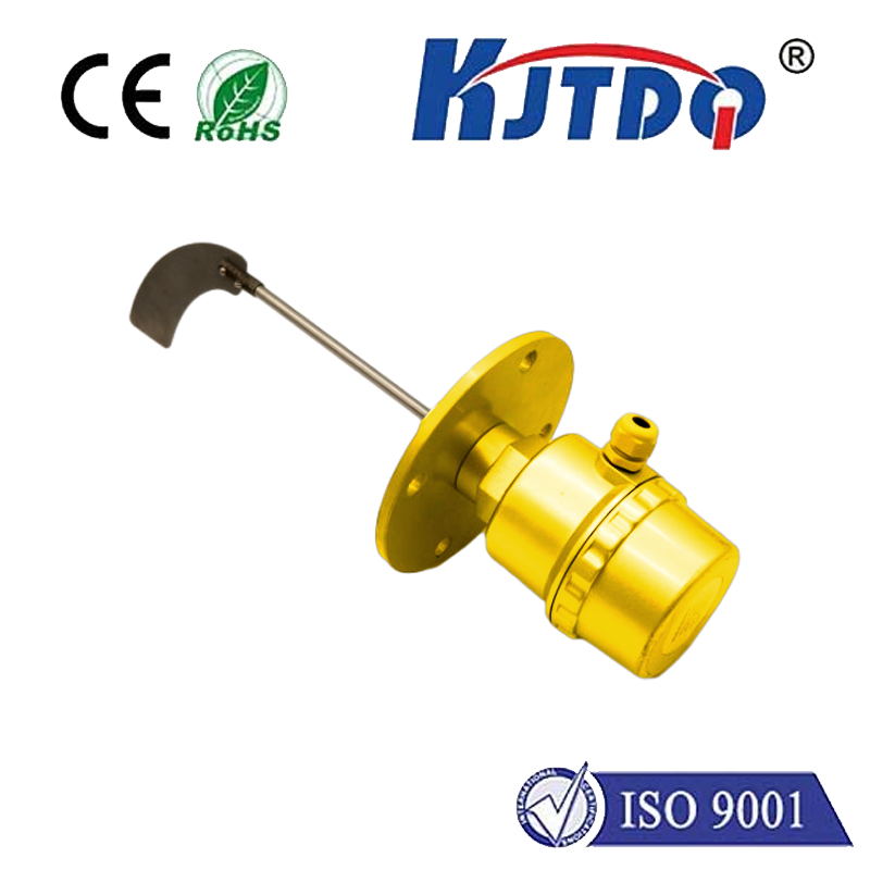
Choosing the right components matters. For the limit switch, consider the mechanical durability and actuation force required. Miniature lever-arm switches are common. For the stepper motor, torque and current ratings must match the load. The driver must be capable of handling the motor's current and should be properly heatsinked. Power supplies must be adequately sized for the motor and the Arduino combined.
Troubleshooting common issues often involves checking connections with a multimeter, ensuring the switch is wired correctly (NO vs. NC), and verifying the logic states in the code match the hardware configuration. Serial communication viaSerial.begin() andSerial.println() statements is invaluable for debugging; you can print the state of the switch pin and the motor's intended actions to the Serial Monitor.
This combination of Arduino, limit switch, and stepper motor opens doors to countless projects. It provides the foundation for safe, calibrated, and repeatable motion control. By mastering this trio, you move from simple static projects to dynamic machines that interact with their physical boundaries intelligently. Start with a simple test on a breadboard, gradually integrating more complex movement patterns and additional switches for both ends of travel, to build a comprehensive and fail-safe motion control system.