
check

check

check

check

check

check

check

check

check

check
Imagine your CNC machine’s spindle head hurtling towards the end of its rails at full speed. Without intervention, it would collide violently, potentially damaging the machine, ruining the workpiece, or causing a safety hazard. This is the nightmare scenario that GRBL limit switches are explicitly designed to prevent. These seemingly simple components are the unsung heroes of CNC operation, acting as the critical last line of defense against catastrophic crashes. Understanding their role within the GRBL ecosystem is paramount for anyone building, maintaining, or operating a GRBL-controlled CNC machine like a router, mill, or laser cutter.
Understanding the GRBL Foundation
GRBL is a high-performance, free, open-source firmware that turns an Arduino (or compatible board) into a full-fledged CNC controller. It interprets G-code commands (the language CNC machines understand) and translates them into precise electrical signals that drive the machine’s motors. Renowned for its efficiency, accuracy, and active community support, GRBL powers countless DIY and professional CNC machines worldwide. Its core function is motion control, ensuring the tool moves exactly where and how the design dictates.
The Crucial Role of Limit Switches
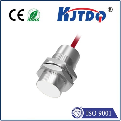
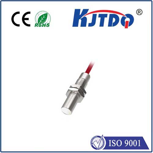
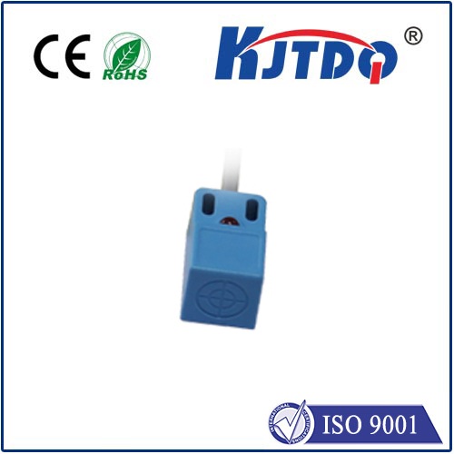
Limit switches are physical sensors strategically placed at the extreme ends (limits) of each axis of movement on a CNC machine (X, Y, and Z). Their primary purpose is simple yet vital: to detect when the machine’s moving parts (like the gantry or spindle carriage) reach the physical boundaries of their intended travel.

Here’s how they fundamentally work:
ALARM state (usually Alarm:1 for hard limits). This locks out further movement via normal G-code commands.$H command). Homing uses separate homing switches (often the same physical switches configured differently in GRBL, or dedicated ones) to find a precise, repeatable starting point (machine zero).Beyond Basic Crash Prevention: Homing
While preventing crashes is their most dramatic function, GRBL limit switches are intrinsically linked to another critical process: homing. As mentioned, after a limit is triggered, homing is required.
$H): When initiated, GRBL slowly moves each axis towards its home position until the corresponding homing switch is triggered. It then backs off slightly and precisely locates the switch edge again (using a slower speed) to establish a highly accurate Machine Zero coordinate. This process eliminates positional drift and ensures every job starts from a known, reliable position. Rigorous homing is fundamental for achieving consistent, accurate CNC machining results.Integrating Limit Switches with GRBL: Key Considerations
Successfully implementing limit switches requires careful attention:
$5, $21, $22 etc.) match your physical switch wiring.$20 and $21.$25), but sometimes additional hardware debouncing (capacitors/resistors) is needed for reliable operation.Why You Absolutely Need GRBL Limit Switches
The benefits extend far beyond preventing that catastrophic crash:
Implementing the Safety Net
Neglecting GRBL limit switches is a significant risk for any GRBL-controlled CNC machine. They are not an optional accessory; they are a fundamental component of a safe, reliable, and professional setup. Whether you are building a machine from scratch or restoring an old one, investing time in correctly selecting, wiring, configuring ($ settings), and testing your limit switches is an investment in protecting your hardware, your work, and your safety. Configured correctly within the GRBL firmware, these humble switches become the vigilant guardians that allow your CNC machine to operate confidently at the edge of its capabilities.
