gravity limit switch for hoist
- time:2025-08-04 12:43:40
- Click:0
Gravity Limit Switch for Hoist: Your Essential Defense Against Over-Lowering Disasters
Picture this: a heavy load descends smoothly from a warehouse hoist. Below, workers are preoccupied. Suddenly, a grinding crash echoes as the hook block plummets uncontrollably, striking equipment or, catastrophically, the floor itself. The potential for severe damage, costly downtime, and most critically, devastating injury is horrifyingly real. This nightmare scenario is precisely what the gravity limit switch for hoist is engineered to prevent. Often an unsung hero in material handling safety, this critical device stands as the final, reliable barrier against the grave dangers of over-lowering. Forget generic “limit switch” jargon – understanding the specific role and value of the gravity limit switch is paramount for anyone responsible for hoist operation and safety.
Understanding the Peril: The Risks of Uncontrolled Descent
Hoists are powerful tools designed for vertical lifting and lowering. While upper travel limits prevent the load block from colliding with the hoist’s superstructure or winding onto the drum (another critical safety function), the opposite danger – descending too far – is equally hazardous. Over-lowering consequences are stark:
- Load Block/Sheave Collision: The hook assembly or load block crashing into the hoist base, drum, or ground support. This causes immediate physical damage to the block, sheaves, wire rope, and potentially the hoist framework.
- Load Crushing/Dropping: If the load itself hits an obstruction or the ground unexpectedly while still suspended, it can destabilize, crush objects beneath it, or even cause the load to drop entirely.
- Structural Damage: The immense impact force can transmit shockwaves through the hoist structure, leading to cracks, misalignment, or long-term fatigue failures.
- Personnel Injury or Fatality: This is the ultimate and most unacceptable risk. Workers near the lower travel path are in extreme danger if over-lowering occurs.
Conventional upper limit switches don’t protect against this downward trajectory. That’s where the gravity limit switch earns its indispensable role.

The Solution: How a Gravity Limit Switch Safeguards Operations
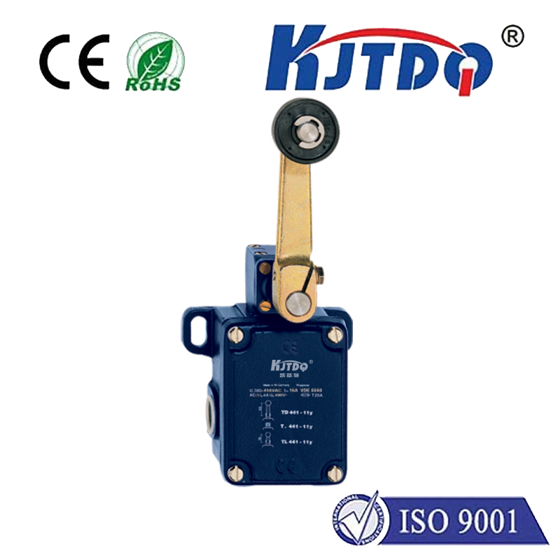
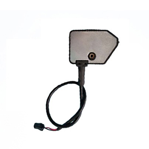
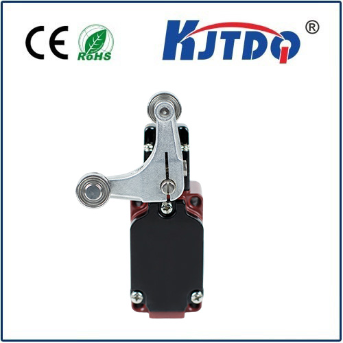
Unlike electrically activated sensors monitoring rope wraps or drum turns, a gravity limit switch operates on a beautifully simple, inherently reliable mechanical principle. It is physically mounted near the lowest safe point the hook block should ever reach. Typically, a lever arm protrudes into the hook block’s descent path.
- Descent: As the hook block lowers, it eventually makes contact with the lever arm of the gravity switch.
- Activation: The downward force exerted by the descending block pushes against the lever arm.
- Circuit Interruption: This physical movement actuates a switch mechanism (often a heavy-duty snap-action switch) inside the gravity switch housing. This switch is wired directly into the hoist’s control circuit.
- Power Cutoff: The actuation of the internal switch opens the control circuit responsible for the downward motion of the hoist. This immediately cuts power to the hoist motor’s lowering function, stopping the descent before the hook block reaches its collision point.
- Fail-Safe Nature: Crucially, this mechanism is often gravity-dependent and inherently failsafe. If the lever arm is pushed (or if a linkage fails in certain designs), it will trigger the switch to open. It doesn’t rely on spring pressure to return to a safe state – gravity ensures the switch activates when the lever is depressed. Power must be manually reset (often by raising the hook block) before descent can resume.
Why Choose a Gravity Limit Switch? Key Advantages
The gravity limit switch offers unique benefits that make it the preferred solution for lower-limit protection in many hoisting applications:
- Complete Independence from Hoist Operation: Since it’s triggered by the physical presence of the hook block itself, it functions regardless of how the hoist is being operated (manual pendant, radio control, automated system) or any potential malfunction in rope-wrap counters or upper limit systems. Its activation is absolute and based on position.
- Failsafe Design: As mentioned, the typical design means that any interruption of the lever’s normal position (usually horizontal) causes the switch to open the lowering circuit. Failure modes generally lead to a safe shutdown.
- High Reliability: With robust mechanical construction using durable materials to withstand industrial environments (dust, moisture, vibration), and minimal complex electronics, gravity switches are renowned for long-term, dependable service.
- Clear Physical Indication: Operators can easily visually confirm if the hook block has engaged the lever arm.
- Critical Redundancy: It provides a vital layer of safety independent of the hoist’s primary control systems or other limit switches. This redundancy is fundamental to robust safety protocols.
Installation and Maintenance: Ensuring Peak Performance
For a gravity limit switch to function correctly, proper installation and maintenance are non-negotiable:
- Precise Positioning: Mounting location is critical. It must be positioned such that the lever arm is engaged before the hook block or its lowest attached component (like a lower sheave block) can strike any obstruction or the drum. Careful measurement during installation is key.
- Secure Mounting: The bracket and switch housing must be rigidly fixed to a stable part of the hoist structure to prevent deflection or movement that could alter the trip point.
- Environmental Protection: While robust, the switch should be located away from direct streams of water, excessive chemical splashes, or extreme heat sources beyond its specified rating. Conduit entries must be sealed.
- Regular Inspection & Testing: This is crucial. Procedures should include:
- Visual inspection for physical damage, corrosion, or loose mounting.
- Manual operation test: Carefully push the lever arm (ensure hoist power is isolated!) and verify that:
- The switch mechanism actuates crisply.
- The lowering direction circuit is positively interrupted.
- An audible “click” is often present.
- The hoist cannot be operated in the lowering direction until the switch is reset (hook raised).
- Operational Test: Periodically running the hook block down until it safely trips the switch under controlled conditions is vital confirmation.
- Reset Functionality: After tripping, the switch should automatically reset once the hook block is raised sufficiently clear of the lever arm. Verify this action is smooth and reliable.
Gravity Limit Switch vs. Other Limit Devices: Knowing the Difference
It’s vital to distinguish the gravity limit switch, specifically designed for lower limit protection, from other limit devices:
- Upper Limit Switches: Protect against overwind by stopping upward travel. Usually triggered by rope wraps, rotation counters, or physical contact at the top of travel. They do nothing to prevent over-lowering.
- Rotary Limit Switches: Often used for upper limits, these count revolutions of the hoist drum. While they could theoretically be set for a lower limit, they rely on the hoist’s power and control system for counting accuracy. A mechanical gravity limit switch provides a physically defined, independent lower limit backup. Many safety standards require a physically engaged lower limit device like a gravity switch as the primary or backup protection.
- Magnetic Proximity or Photoelectric Sensors: While sometimes used for positional limits, electronic sensors can potentially fail undetected (e.g


