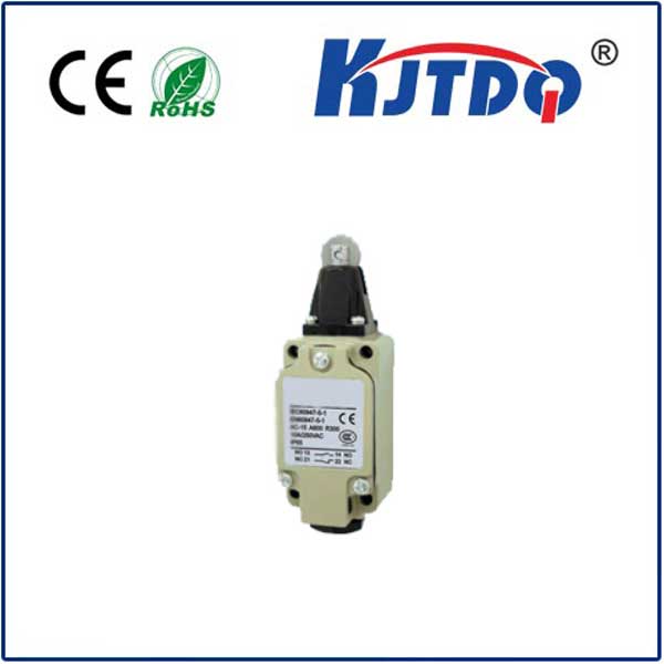
normally open limit switch
- time:2025-08-01 12:20:35
- Click:0
The Normally Open Limit Switch: Operation, Applications and Advantages
Ever wondered how a factory conveyor belt knows exactly when to stop, or how a garage door safely reverses if something blocks its path? Often, the silent sentinel enabling these critical safety and control functions is a humble yet vital component: the normally open (NO) limit switch. Understanding its operation, diverse applications, and inherent advantages is fundamental for anyone involved in automation, machinery design, or maintenance. This article delves into the core principles that make the NO limit switch a cornerstone of precision and safety in countless systems.
At its heart, a limit switch is an electromechanical device designed to detect the presence, absence, or position of an object, or to define the limits of travel for moving parts. The descriptor “normally open” (NO) is crucial, defining its default electrical state when no external force is acting upon it.
- Idle State: In its resting position, untouched by an actuator (like a mechanical lever, roller, plunger, or even a magnetic field), the NO switch’s internal contacts are physically separated. This creates an open circuit between its terminals. Electricity cannot flow through the switch in this state.
- Activated State: When the switch’s actuator is triggered by an object reaching its designated position or limit (e.g., a machine part hits the lever, a door engages the roller), the actuator mechanism physically moves to close the internal contacts. This completes the circuit, allowing electrical current to flow through the switch terminals.
This fundamental behavior – open circuit at rest, closed circuit when activated – forms the core principle behind the normally open limit switch’s operation. The change in state provides a clear, binary signal to a control system (like a PLC - Programmable Logic Controller): “The target object has arrived” or “The travel limit has been reached.”
Mechanically Robust Design
Limit switches are engineered to withstand challenging industrial environments. Common actuator types include:

- Lever Arms: Offer extended reach and can be adjusted for different activation points. Often have rollers to minimize wear.
- Plungers: Provide direct, linear actuation for precise positioning.
- Roller Plungers: Combine linear action with a roller tip for smoother engagement.
- Rotary Actuators: Used for detecting rotary motion limits.
- Wobble Sticks: Sensitive actuators used for detecting small movements or presence.
Housings are typically robust metal or high-impact plastic, offering protection against dust, moisture (varying IP ratings), and impact. The choice of actuator and housing depends heavily on the specific application’s requirements for force, environmental conditions, and precision.
Ubiquitous Applications: Where NO Limit Swifts Shine
The simplicity, reliability, and clear signaling of the normally open configuration make NO limit switches incredibly versatile across numerous industries:
- Position Sensing & End-of-Travel Control: This is the most classic use.
- Machine Tools: Detecting when a milling table or lathe carriage reaches the end of its programmed travel, triggering a stop or direction change. Key for repeatable machining.
- Conveyor Systems: Determining when a package or pallet has reached a transfer point, sorting station, or the end of the line, signaling downstream equipment. Essential for material flow control.
- Robotics: Defining the limits of robotic arm movement to prevent collisions and ensure safe operation within its work envelope. A critical safety component.
- Lifts and Hoists: Signaling when a platform has reached the top or bottom floor, initiating stopping sequences and door interlocks.
- Valve Position: Confirming whether a valve is fully open or fully closed.
- Presence/Absence Detection: While proximity sensors are common, mechanical NO limit switches are often preferred where physical contact is acceptable and robust sensing is needed.
- Door and Gate Monitoring: Detecting if an access panel, safety guard, or gate is properly closed before machinery can be started (safety interlocking).
- Part Feeding: Verifying a part is correctly seated in a fixture before a process begins.
- Sequencing Control: The activation of a NO limit switch can be a prerequisite step in an automated sequence.
- Ensuring a clamp is fully retracted before a workpiece is ejected.
- Confirming a drill head is in the “up” position before the workpiece indexing occurs.
- Safety Monitoring: While specialized safety relays and sensors exist, NO limit switches play vital roles in many safety circuits. For instance:
- Emergency stop pull cords often incorporate NO limit switches wired to break the circuit when pulled.
- Detecting if a safety door is opened, immediately cutting power to hazardous motion.
- The inherent fail-safe nature in some contexts: If a wire breaks on an NO switch used to signal a dangerous condition (like a door open), the circuit remains open, which can be interpreted as the “danger” state, triggering a safe shutdown (though dedicated safety-rated components are essential for high-risk applications).
Why Choose Normally Open? Key Advantages
The preference for a normally open switch configuration often revolves around several compelling benefits:
- Intuitive Signaling: The principle of “circuit made on activation” is straightforward and aligns well with event-triggered logic in control systems (e.g., “Turn on light when door opens”).
- Energy Efficiency: In its default state (no activation), the switch draws no current, preserving energy in systems with many sensors. There is no power dissipation across the open contacts.
- Failsafe Potential (Context Dependent): As mentioned earlier, in critical applications signaling a “danger” condition when activated, a broken wire on an NO sensor can mimic the “danger” signal (open circuit), potentially causing a safe shutdown. However, this is not a substitute for properly certified safety components in high-integrity safety systems. It’s more of a beneficial characteristic in basic monitoring.
- Debounce Simplicity: Mechanical switches can “bounce” (make and break contact rapidly) when actuated. The transition from open to closed is often easier to electrically filter (debounce) than noise on a closed contact.
- Wiring Convenience: In some control panel layouts and PLC input card designs, sourcing or sinking configurations might make wiring NO sensors slightly simpler or more conventional.
- Reliability & Cost: As purely electromechanical devices (in their basic form), NO limit switches are highly reliable, proven over decades, and generally cost-effective solutions for position and limit detection tasks. They offer robust performance in harsh environments where optical sensors might fail.
Integrating with Control Systems:
The signal from an activated NO limit switch is typically fed into a discrete input on a PLC, relay control circuit, or microcontroller. The control system interprets the closed circuit (current flow) as a logical “TRUE” or “ON” signal, signifying that the event the switch is monitoring (position reached, object present) has occurred. This input then triggers the programmed response in the control logic.
In the intricate dance of automation, the normally open limit switch plays a fundamental, reliable role. Its clear-cut behavior – an open circuit at rest, completing the path only when physically triggered – provides an unambiguous signal that machines understand. From safeguarding personnel through safety interlocks to enabling precise positioning in robotic arms and CNC machines, to managing the flow on miles of conveyor belts, the NO limit switch is a testament to the enduring power of robust, well-understood mechanical design. Its simplicity, reliability, cost-effectiveness, and versatile applications ensure its continued relevance in the ever-evolving landscape of industrial control and safety systems. Understanding its operation is key to designing,


