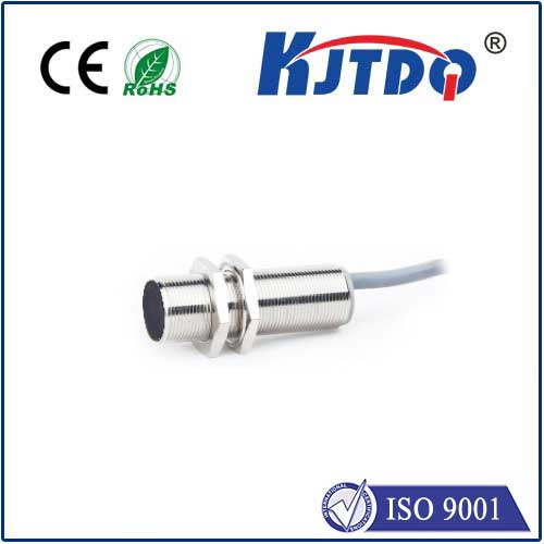
linear actuator with limit switches
- time:2025-07-30 13:41:10
- Click:0
Limit Switches in Linear Actuators: Precision Control and Safety Essentials
Ever wonder how automated factory arms stop precisely at the right spot every single time? Or how medical equipment extends safely without overstraining its mechanisms? The unsung hero enabling this reliability, especially in linear actuators, is often a tiny but critical component: the limit switch. When integrated effectively with linear motion systems, these switches become indispensable for achieving precision and preventing potentially catastrophic failures. Understanding their role is fundamental for anyone designing, using, or maintaining automated systems.
What is a Limit Switch, and Why Does a Linear Actuator Need One?
At its simplest, a limit switch is an electromechanical device designed to detect the presence or absence of an object, or to monitor when that object reaches a specific physical boundary. Within a linear actuator – a device that creates motion in a straight line, typically converting rotary motion (from a motor) into precise linear displacement – limit switches serve two paramount functions:
- Defining Travel Limits: They signal the actuator control system when the extending or retracting mechanism has reached its pre-defined maximum or minimum position. This prevents the actuator from attempting to travel beyond its mechanical boundaries (over-extension or over-retraction), which could cause severe damage to the actuator itself (like stripping gears or bending rods), the load it’s moving, or surrounding equipment.
- Enabling Precision Positioning: While primarily known for defining endpoints, limit switches can also be strategically placed to signal intermediate positions. This allows the control system to initiate specific actions precisely when the linear actuator reaches certain points in its stroke (e.g., slowing down, starting a secondary process, or changing direction).
Without properly configured limit switches, an electric linear actuator relies solely on motor current sensing or internal software limits for stoppage. While these methods offer some protection, they are far less reliable than a physical switch triggered by actual position. A jammed load or unexpected resistance might not sufficiently increase motor current to trigger an overload cut-off before damage occurs. Software limits can be vulnerable to programming errors or signal interference. Limit switches provide a robust, physical confirmation of position, a vital safety feature.
How Linear Actuator Limit Switches Work: The Core Mechanism

The integration is generally straightforward:
- Switch Placement: The limit switch (or switches, one for each end of travel, and potentially more for intermediates) is mounted within the linear actuator housing or externally on the application structure.
- Trigger Mechanism: As the actuator’s moving part (like the drive nut or rod collar) travels along its linear path, it eventually contacts a physical actuator lever (plunger, roller lever) on the switch. Alternatively, in non-contact types, it moves into the detection zone.
- Electrical Signal: This contact (or proximity) causes the limit switch to change its internal electrical state – usually opening or closing a circuit.
- Control System Action: The actuator’s controller (PLC, motor controller, or simple relay circuit) detects this signal change. It then immediately sends a command to stop or reverse the motor driving the actuator.
- Hard Stop: The actuator comes to a controlled halt at the precise location defined by the switch.
This creates a “hard stop” – a fundamental fail-safe based on physical position, drastically enhancing actuator reliability and longevity.
Common Types of Limit Switches Used in Linear Actuators
Different applications demand different sensing technologies. The most prevalent types include:
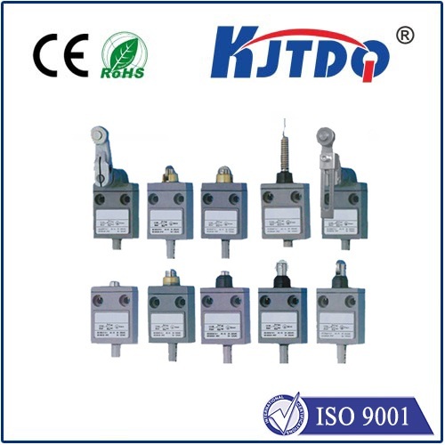
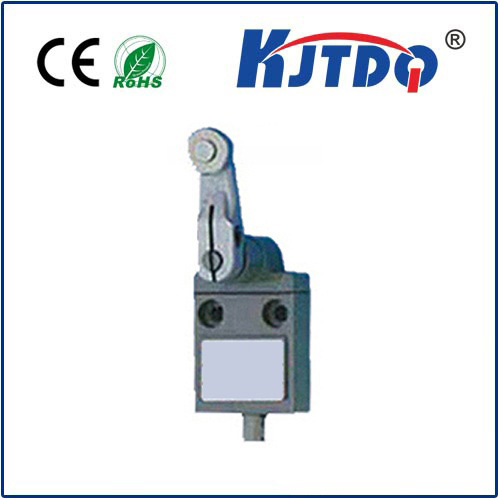
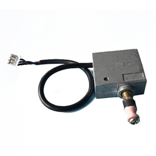
- Mechanical Contact Switches (Lever/Plunger/Roller): The most traditional and robust type. A physical moving part on the actuator presses against a lever, plunger, or roller arm on the switch, physically actuating the electrical contacts inside. Pros: Highly reliable, relatively low cost, simple operation, can handle high currents. Cons: Mechanical wear over time, potential for contact bounce (electrical chatter), susceptible to contamination in harsh environments. Vital for providing a definitive mechanical stop signal.
- Magnetic Reed Switches (Proximity): A small magnet is mounted on the actuator’s moving part. When this magnet passes very close to the fixed reed switch mounted in the housing, the magnetic field causes the thin, hermetically sealed metal reeds inside to flex and make contact. Pros: Completely sealed from dust and moisture (high IP ratings like IP67/IP69K common), no moving parts to mechanically wear out, fast switching, long lifespan. Cons: Limited sensing range (requires very close proximity), susceptible to strong external magnetic fields, generally handle lower currents than mechanical switches. Excellent for linear actuators needing environmental sealing.
- Hall Effect Sensors (Proximity): Similar concept to reed switches but using semiconductor technology. A magnet on the moving part triggers a change in voltage output from the sensor as it passes by. Requires integrated electronics. Pros: Solid-state reliability, high switching frequency, precise switching point, sealed designs available. Cons: Typically more expensive than reed switches, requires a power supply and conditioning circuitry. Offers precise position sensing.
- Optical Sensors (Proximity): Use an infrared light beam and a receiver. Triggered when the actuator’s moving part (or a flag on it) breaks the beam. Pros: Very fast, non-contact, precise. Cons: Susceptible to dirt, dust, fog, or other occlusions affecting the light beam; generally more expensive and complex. Less common for purely endpoint safety stops due to reliability concerns in dirty environments.
Beyond Endpoints: Safety, Efficiency, and Control
While defining travel limits is their primary safety role in electric linear actuators, limit switches contribute significantly to overall system performance:
- Collision Avoidance: In complex machinery with multiple actuators, limit switches prevent axes from colliding by defining their respective safe zones, a critical operational safety feature.
- Machine Safety Interlocks: They can be integrated into larger safety circuits, ensuring guards are closed or unsafe areas are clear before allowing actuator movement.
- Homing Sequences: On startup, many automated systems use the “home” position (often defined by a limit switch) as a reliable reference point for all subsequent positioning commands, ensuring system accuracy.
- Energy Efficiency: Preventing pointless straining against hard stops reduces wear but also prevents motors drawing excessive current unnecessarily.
- Process Control: Intermediate limit switches can initiate process steps with high timing or positioning accuracy.
Choosing the Right Limit Switch for Your Linear Actuator
Selecting the optimal limit switch depends heavily on the application:
- Environmental Conditions: Dust, moisture, chemicals, temperature extremes, and washdown requirements dictate IP (Ingress Protection) ratings and material choices. Magnetic reed or Hall effect sensors excel in harsh conditions.
- Required Precision: How critical is the absolute stop point? Some switches (like certain mechanical levers) have inherent “travel” before actuation.
- Durability Needs: High cycle rates demand switches rated for millions of operations (often Reed or Hall Effect).
- Electrical Load: The voltage and current (amperage) the switch must handle for the control signal. Mechanical switches often handle higher currents.
- Mounting Constraints: Available space within the linear actuator assembly or externally.
- Cost: Balance required performance with budget.
Conclusion: A Foundational Element for Reliable Automation
While often hidden within the housing, the humble limit switch is a cornerstone of safe, reliable, and precise linear actuator operation. By


