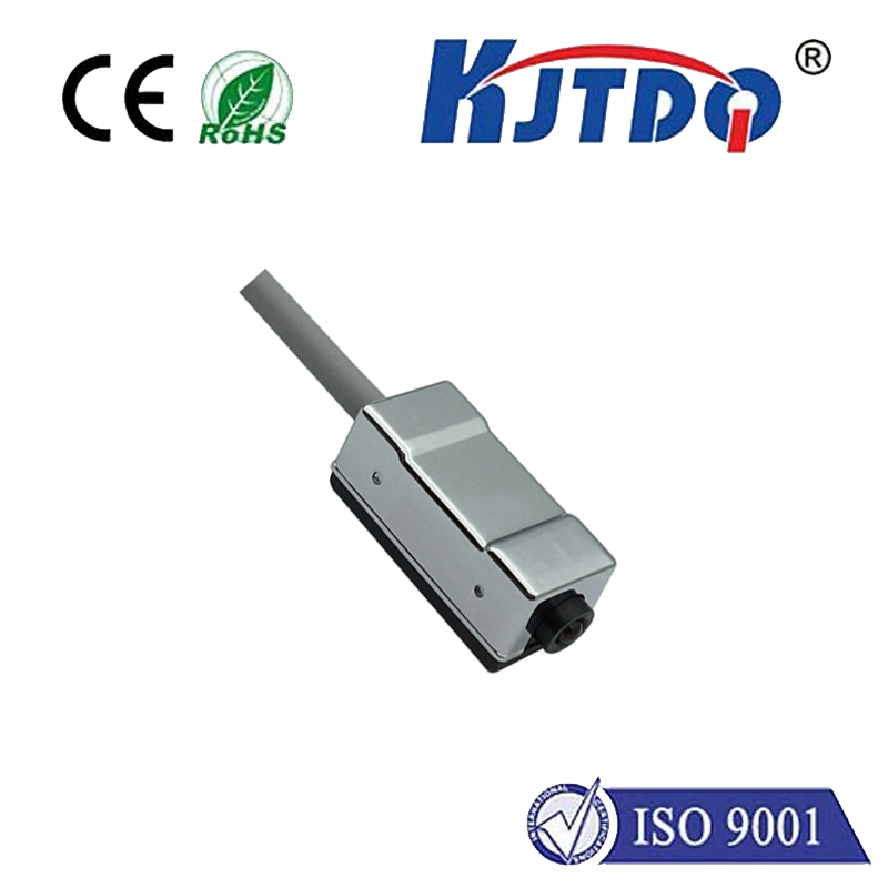
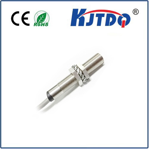
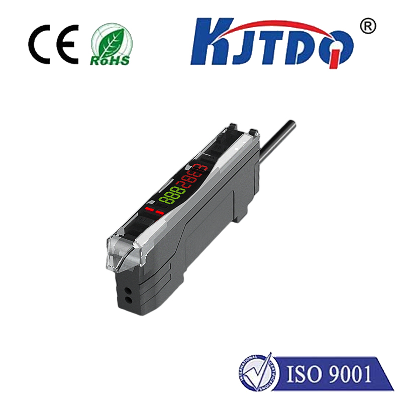
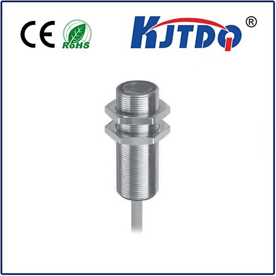
sensor pnp 24vdc
- time:2025-07-17 08:24:29
- Click:0
Sensor PNP 24VDC: Your Guide to Sourcing Output Industrial Sensors
Ever wired up a sensor only to find your PLC input stubbornly refuses to recognize its signal? Or worse, seen a brief spark and that pungent smell of fried electronics? If you’re working with industrial automation, particularly sensors labeled “PNP 24VDC,” understanding precisely what this means isn’t just technical jargon – it’s the difference between smooth operation and costly downtime.
The designation “sensor PNP 24VDC” packs essential information into a compact label. It defines the sensor’s core electrical characteristics: its output switching type (PNP) and its required operating supply voltage (24 Volts Direct Current). Grasping these fundamentals is crucial for correct installation, reliable operation, and seamless integration into control systems. Let’s demystify the PNP 24VDC sensor.
Decoding “PNP”: The Sourcing Output Principle
PNP stands for Positive-Positive-Positive, referring to the transistor configuration inside the sensor responsible for switching the output signal. More intuitively, it signifies a “sourcing” output.
- How it Works: When the PNP sensor is active (detects its target), its output terminal internally connects to the positive supply voltage (24VDC+) via the PNP transistor. Essentially, it sources positive current from its output terminal to the load (like a PLC input).
- The Load Connection: The load (e.g., PLC input module) must be connected between the sensor’s output terminal and the DC common (0V or Ground). When the sensor activates, it completes the circuit: 24VDC+ flows out of the sensor output, through the load, and back to the DC common, providing the signal.
- Symbol: Look for the IEC symbol depicting a switch (the transistor) connecting the output to the positive supply rail (+V).
Why PNP Dominates Many Regions & PLC Inputs
PNP sensors are often preferred and sometimes mandated because they align perfectly with typical sinking PLC input modules. Here’s the synergy:
- Sinking Input Compatibility: Most PLC input modules are designed as sinking inputs. This means they expect a positive voltage (relative to their common terminal) to be fed into their input point to signify an “ON” state.
- Sourcing Sensor Matches Sinking Input: A PNP (sourcing) sensor provides this positive voltage from its output when active. Connect the PNP sensor output to the PLC input terminal, and the PLC common to the DC supply common (0V). When the sensor activates, it sources current directly into the sinking PLC input, signaling correctly.
The Critical Role of “24VDC”: Powering Your Sensor
This part of the label specifies the sensor’s operating voltage range. 24 Volts DC is the absolute standard in industrial automation control circuits for numerous compelling reasons:
- Safety: Compared to higher AC voltages (like 120VAC or 230VAC), 24VDC is considered Intrinsically Safe (IS) or at least poses a significantly lower risk of severe electric shock in industrial environments. This enhances operator safety during maintenance or troubleshooting.
- Component Compatibility: PLCs, relays, valves, countless other automation devices, and crucially their input/output (I/O) modules, are predominantly designed around 24VDC logic levels. Using the same voltage across the system simplifies design, wiring, and component selection.
- Noise Immunity: DC voltages are inherently less susceptible to electromagnetic interference (EMI) compared to AC signals. This is vital in industrial settings filled with motors, drives, and high-power switching equipment that generate significant electrical noise. 24VDC provides a robust signal level that can resist this noise better than lower DC voltages (like 5V or 12V).
- Standardization & Cost: The widespread adoption of 24VDC has led to economies of scale, making power supplies, wiring, and compatible components readily available and cost-effective.
Key Considerations When Using PNP 24VDC Sensors
- Polarity Matters! ALWAYS observe proper wiring:
- Brown Wire: Connect to +24VDC (Positive Supply).
- Blue Wire: Connect to 0VDC (DC Common, Ground).
- Black Wire: Connect to the Load (e.g., PLC Input). This is the sourcing output.
- White Wire: (If present) Often used for an inverse output, diagnostic signal, or function select. Consult the datasheet!
- Reversing power polarity is a common cause of immediate sensor failure. Double-check your connections!
- PLC Input Type: While PNP sensors are ideal for sinking PLC inputs, ensure your specific PLC module accepts a sourcing input signal. Most modern modules can be configured or inherently support both, but verification is essential. Connecting a PNP sensor to a PLC input only designed for NPN (sourcing input) circuitry will not work.
- Load Compatibility: The sensor’s datasheet specifies its maximum load current. Ensure the device connected to the output (PLC input, relay coil, etc.) does not exceed this limit. Overloading can damage the sensor’s output transistor.
- Shielding & Noise: While 24VDC is robust, proper installation practices are crucial. Use shielded cable for analog sensors or for long cable runs in noisy environments. Connect the shield properly (usually at one end only, often the control panel end) to the reference ground/chassis. Avoid routing sensor cables parallel to high-power AC lines.
- Diagnostics: Many modern PNP 24VDC sensors incorporate diagnostic LEDs (power and output status). These provide immediate visual feedback on sensor operation and target detection, significantly speeding up commissioning and troubleshooting.
Common Applications of PNP 24VDC Sensors
Their reliability and standard voltage make PNP 24VDC sensors ubiquitous:
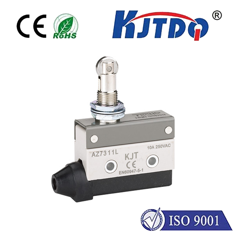
- Position Detection: Limit switches (inductive, capacitive, optical) confirming cylinder positions, machine stops.
- Object Presence/Absence: Detecting parts on a conveyor (photoelectric sensors), material in a bin (capacitive sensors), or pallets at a station (ultrasonic sensors).
- Level Sensing: Monitoring fluid levels in tanks (ultrasonic, capacitive).
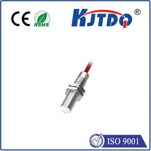
- Speed Monitoring: Counting rotations (inductive proximity sensors near gear teeth).
- Safety Interlocks: Confirming guard doors are closed (magnetic reed switches or safety-rated proximity sensors).
- Assembly Verification: Ensuring components are present and correctly oriented before a process step.
Troubleshooting Tip: If your PNP 24VDC sensor seems unresponsive, methodically check:
- Power: Is 24VDC present between Brown (+) and Blue (-)?
- Wiring: Are the Brown, Blue, and Black wires connected correctly?
- Target: Is the sensor positioned correctly to detect the target material? (Check sensing distance, target size/material requirements).
- Load: Disconnect the output lead (Black wire) from the load. Place a multimeter set to DC voltage between the Black wire and Blue wire. When the sensor activates, you should read close to 24VDC. If you do, the sensor is likely working, and the issue lies with the load (PLC input configuration, wiring to PLC unit, or a faulty PLC input point). If you don’t read voltage, the sensor output stage may be faulty.
5.


