check

check

check

check
check

check
check
check
check
check
In the intricate symphony of modern automation, proximity sensors are the silent sentinels. They detect the presence or absence of objects without physical contact, triggering actions vital to countless processes. But when you delve into the specifications, two terms frequently appear: PNP and NPN. This isn’t just technical jargon; it represents a fundamental choice in how your sensor interfaces with the control system. Understanding the difference between PNP vs NPN proximity sensors is absolutely critical for ensuring smooth operation, avoiding wiring headaches, and preventing potential damage. This guide cuts through the complexity, explaining what these terms mean, how they work, and how to choose the right one for your application.
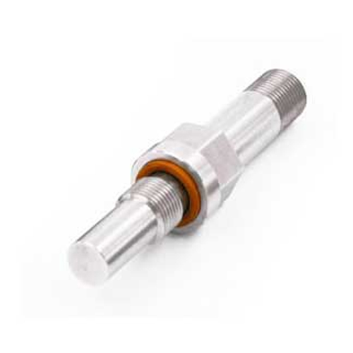
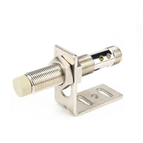
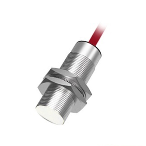
The Inductive Proximity Sensor: A Quick Refresher
While PNP and NPN define the output switching type, it’s essential to recall how common inductive proximity sensors operate. These sensors generate an electromagnetic field. When a metallic target enters this field, it induces eddy currents within the target, causing a change in the sensor’s internal electrical circuit (like an oscillator). This change is detected and processed, leading to the sensor switching its output state – essentially turning its output signal “ON” or “OFF.” The core distinction between PNP and NPN lies precisely in how they manage this switched output signal relative to the power supply.
The Heart of the Matter: Sourcing (PNP) vs. Sinking (NPN)
The labels PNP and NPN refer to the type of transistor used in the sensor’s output stage. This transistor acts as the electronic switch controlling the output signal. The key difference boils down to whether the sensor provides the positive voltage path (source) or provides the ground path (sink) when activated.
PNP vs NPN: A Side-by-Side Comparison
| Feature | PNP Sensor (Sourcing) | NPN Sensor (Sinking) |
|---|---|---|
| Output Type | Sources Positive Voltage (+V) | Sinks Current to Ground (0V) |
| NO Operation | Output = +V when active (target present) | Output = 0V when active (target present) |
| Output State (Active) | High Signal (closer to +V) | Low Signal (closer to 0V) |
| Wiring Load | Load connected between OUT and 0V | Load connected between +V and OUT |
| Current Flow (On) | From Sensor OUT -> Through Load -> To 0V | From +V -> Through Load -> To Sensor OUT -> To 0V |
| Common Nickname | Positive Switching | Negative Switching |
Choosing Between PNP and NPN: It’s All About Compatibility
There’s no inherent “better” type; the right choice depends entirely on the input requirements of the device your proximity sensor is connected to, typically a Programmable Logic Controller (PLC) or another controller.
PLC Input Cards Rule the Decision:
Sinking Input Cards: These PLC inputs require a PNP sensor. The input card provides the connection to ground (0V) internally. A PNP sensor, when active, sources the positive voltage (+V) to the input point, completing the circuit internally to the card’s ground.
Sourcing Input Cards: These PLC inputs require an NPN sensor. The input card is internally connected to the positive supply voltage (+V). An NPN sensor, when active, provides the path to ground (0V), allowing current to flow from the card’s internal +V, through its input circuit, out to the sensor’s output, and down to ground.
Key Considerations:
Always Consult the PLC Manual! This is non-negotiable. Identify whether your PLC’s digital input modules are specified as “Sinking” or “Sourcing”. This information is paramount.
Industry & Regional Preferences: While not a hard rule, PNP sensors are often more common in European and North American designs, while NPN sensors see significant use in Asian markets. Knowing your PLC’s requirement trumps regional trends.
Circuit Design Philosophy: Some designers prefer the conceptual simplicity of having the sensor provide the active “high” signal (PNP). Others find the safety aspect of an NPN sensor (where an active state pulls the line low, less susceptible to false triggering by noise on a positive line) appealing in certain noisy environments, though modern sensors mitigate this well. The overriding factor remains PLC input compatibility.
Wiring Looms: Consistency helps prevent errors. If most sensors on a machine use one type, stick with it unless a specific input card forces a different choice.
Wiring Essentials: Getting it Right
Mixing PNP and NPN sensors incorrectly is a common source of failure. Remember these core principles:
1