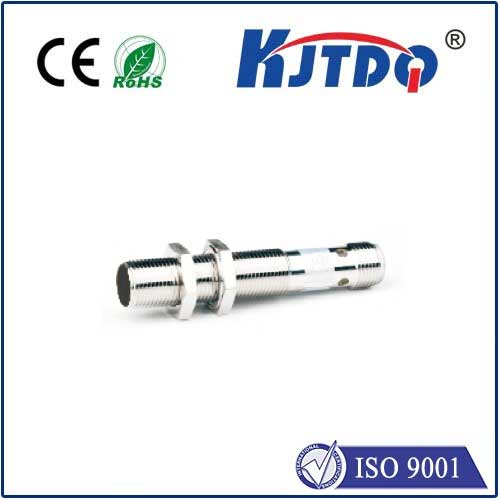
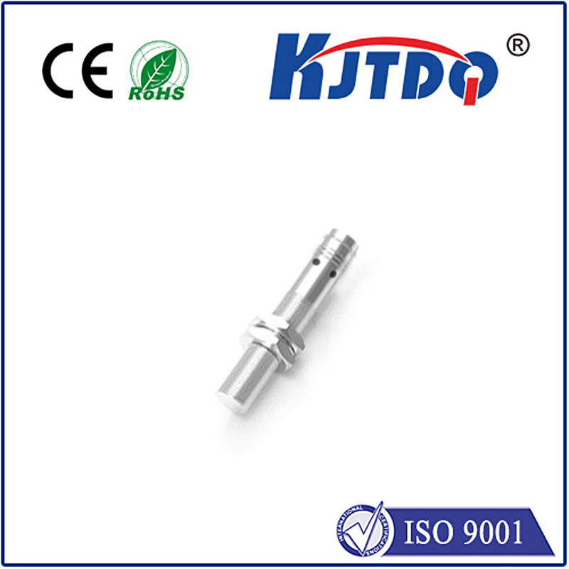
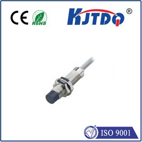
proximity probe sensor
- time:2025-07-15 08:19:37
- Click:0
Proximity Probe Sensors: The Unseen Guardians of Rotating Machinery Health
Imagine monitoring the heartbeat of a massive turbine or the subtle vibrations of a high-speed compressor shaft without ever touching it. In the demanding world of industrial machinery, where precision is paramount and failures are costly, proximity probe sensors achieve precisely this feat. These unassuming devices are the linchpins of predictive maintenance, enabling engineers to detect potential problems before they escalate into catastrophic downtime. Understanding their function and application is crucial for maximizing the reliability and lifespan of critical rotating assets.
Beyond Simple Presence Detection: Precision Measurement
While often grouped under the broader “proximity sensor” umbrella, proximity probe sensors (PPS) are distinct in their purpose and capability. Unlike standard inductive proximity sensors designed for simple on/off detection of nearby metal objects, proximity probes are engineered for high-precision measurement. Their primary role is to continuously and non-contactly monitor two critical parameters of rotating shafts:
- Radial Vibration: The side-to-side movement of the shaft within its bearing clearance.
- Axial Position/Thrust: The movement of the shaft along its axis (in and out).
This capability makes them indispensable for condition monitoring in applications like turbines, compressors, pumps, motors, and gearboxes.
The Eddy Current Principle: How Proximity Probes See Without Touching
The core technology behind most industrial proximity probe sensors is eddy current induction. Here’s how it works:
- The Probe: The sensor tip contains a coil of fine wire energized by a high-frequency alternating current (AC) from an oscillator circuit within an associated proximitor (the driver/conditioner module).
- Generating the Field: This energized coil generates a small, high-frequency electromagnetic field that radiates out from the probe tip.
- Inducing Eddy Currents: When this field encounters a conductive target (typically the rotating shaft), it induces circulating electrical currents called eddy currents within the surface layer of the target material.
- Field Interaction & Energy Loss: These eddy currents, in turn, generate their own opposing magnetic field. This interaction dampens the original field from the probe coil and effectively changes the coil’s impedance (a combination of resistance and inductance).
- Distance Modulation: Crucially, the strength of the eddy currents, and thus the degree of damping and impedance change, is directly proportional to the distance (gap) between the probe tip and the target surface. A smaller gap creates stronger eddy currents and more damping.
- Signal Conversion: The proximitor module constantly monitors the change in the probe coil’s impedance. It processes this change and converts it into a calibrated, linear DC voltage output signal (e.g., -2V to -18V or 0V to 10V). This output voltage is a precise analog representation of the gap distance.
Why Proximity Probe Sensors Rule Industrial Monitoring
The non-contact nature of PPS offers compelling advantages over traditional contact sensors like accelerometers (for vibration) or LVDTs (for position) in many rotating machinery scenarios:
- No Mass Loading: Since they don’t touch the shaft, they add zero mechanical load, avoiding any distortion of the very vibration or position they are measuring, critical for high-speed or lightweight shafts.
- Direct Shaft Relative Measurement: They measure the shaft’s motion relative to the bearing housing where they are mounted. This is vital for assessing bearing health and actual shaft movement within the clearance.
- High Resolution and Frequency Response: Capable of resolving movements down to microns (µm) and capturing very high-frequency events (often DC to 10 kHz or higher), essential for detecting subtle imbalances, misalignments, or friction problems.
- Robustness in Harsh Environments: Properly selected probes are designed to withstand high temperatures, pressure, oil, steam, and other challenging conditions common in industrial settings.
- Absolute Position Data: They provide DC-coupled measurement, meaning they give true position data relative to a physical gap, not just the AC vibration component. This is crucial for monitoring slow changes like thermal growth or thrust position.
Vital Applications: Where Precision Gap Measurement Matters
Proximity probe sensors find critical use in numerous areas:
- Rotating Machinery Protection: Continuously monitoring radial vibration and axial position against predefined alarm and trip thresholds in turbomachinery to prevent catastrophic failures.
- Condition-Based Maintenance (CbM): Providing the high-fidelity data needed for vibration analysis programs, identifying developing faults like imbalance, misalignment, bearing wear, shaft cracks, and oil whirl/whip.
- Thrust Bearing Monitoring: Precisely measuring shaft axial position to prevent thrust bearing failure due to excessive load.
- Differential Expansion Measurement: Monitoring the difference in thermal growth between a turbine rotor and its casing.
- Eccentricity/Centering: Measuring shaft bow or position relative to bearings during start-up/shutdown (slow roll).
- Speed Measurement / Keyphasor®: Providing a once-per-revolution timing pulse (via a keyway or notch on the shaft) for phase analysis of vibration data.
Selecting and Implementing Proximity Probes: Key Considerations
Success with proximity probe sensors hinges on diligent selection, installation, and calibration:
- Target Material: The sensor must be calibrated for the specific conductivity and permeability of the target material (e.g., steel alloys behave differently than aluminum or stainless steel).
- Operating Temperature: Both the probe and its cabling must be rated for the ambient and possible surface temperatures. High-temperature probes use specialized cables.
- Probe Size & Range: Probe diameter relates to its sensing range and required target area. Standard sizes are 5mm, 8mm, and 11mm. Choosing the correct nominal gap setting (often 0.8-1.5mm for 8mm probes) is critical for optimal linearity.
- Mounting & Stability: The probe must be securely mounted in a rigid, vibration-free holder. Mechanical runout of the target surface must be minimized.
- Calibration & Gap Voltage: The system (probe + cable + proximitor) must be precisely calibrated using a calibration curve specific to the probe and target material. Monitoring the DC gap voltage is essential for correct operation.
- Cabling Integrity: Extension cables must be the correct type, undamaged, and properly connected to avoid signal degradation. Radio Frequency Interference (RFI) shielding is vital.
- Proximitor Selection: The driver/conditioner module must match the probe and cable requirements and provide the necessary power, scaling, and output signals.
The Silent Workhorse Enabling Reliability
Proximity probe sensors are far more than simple detectors. They are sophisticated measurement instruments operating on well-understood physical principles, delivering the precise non-contact gap measurement data that forms the bedrock of modern rotating machinery health monitoring. By enabling engineers to detect minute changes in vibration and position long before they become catastrophic, proximity probe sensor systems are truly the silent guardians, safeguarding billions of dollars worth of industrial assets and ensuring operational continuity. Their critical role in predictive maintenance continues to expand as industries strive for ever-greater efficiency and reliability. Understanding their operation and proper application is fundamental for any professional involved in machinery health and safety.


