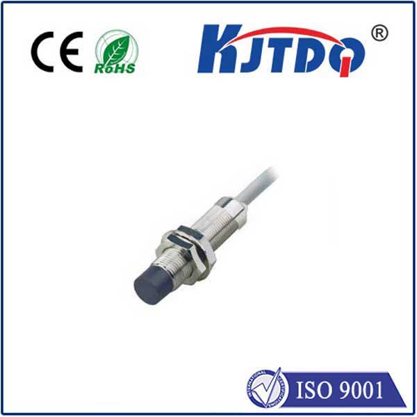
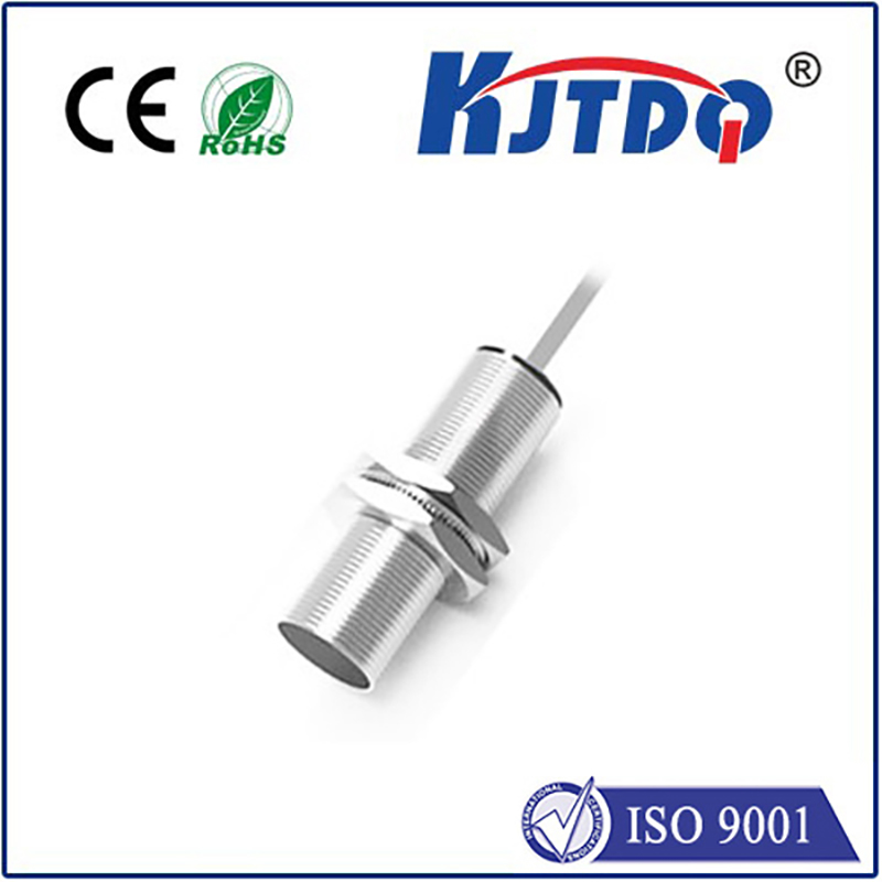
inductive sensor pnp
- time:2025-07-12 01:59:43
- Click:0
Demystifying PNP Inductive Sensors: The Workhorse of Proximity Detection
Automation thrives on sensing the unseen. Whether it’s counting bottles on a high-speed line, confirming a robotic arm’s position, or detecting metal parts on a conveyor, reliable proximity detection is fundamental. Among the plethora of sensors available, the inductive proximity sensor stands out for its robustness in harsh industrial environments, especially when dealing with metallic objects. And within this family, the PNP inductive sensor configuration reigns supreme in many global markets. Let’s delve into what makes this sensor type so crucial.
Understanding the Core: Inductive Sensing
At its heart, an inductive proximity sensor operates on the principles of electromagnetism. It contains an oscillator circuit generating a high-frequency electromagnetic field emanating from its active face. When a metallic target (like steel, aluminum, copper, brass, etc.) enters this field, eddy currents are induced on the target’s surface. These eddy currents draw energy from the sensor’s oscillator, causing its amplitude to decrease. An integrated evaluation circuit detects this amplitude reduction, triggering a change in the sensor’s output state. Crucially, this contactless detection requires no physical touch, minimizing wear and tear.
The Crucial “P” in PNP: Output Configuration Explained
Now, let’s unravel the “PNP” designation. This refers to the transistor output type and its switching behavior within the sensor’s output circuit. Transistors act as electronic switches. PNP and NPN describe the type of bipolar junction transistor used:

- PNP Transistor: A PNP transistor switches the positive supply voltage (typically +24V DC, the industry standard) to the load connected to its output wire.
- NPN Transistor: Conversely, an NPN transistor switches the negative supply voltage (0V or ground) to the load.
This distinction leads to the key difference in wiring and operation:
- PNP (Sourcing) Operation:
- The sensor has three wires: Brown (+Voltage Supply), Blue (0V/Common), and Black (Output Signal).
- When no target is present, the output transistor is OFF. The Black wire is not connected internally to the Brown (+V) wire. The output signal is effectively open or floating relative to +V.
- When a metallic target enters the sensing range, the PNP transistor switches ON. This internally connects the Black output wire to the Brown (+V) wire.
- Current now flows from the sensor’s output (Black wire) through the connected load (e.g., a PLC input, relay coil, indicator lamp) and then back to the power supply’s negative (Blue wire). In essence, the PNP sensor sources the positive current to the load.
Why PNP Inductive Sensors Dominate Many Applications
The PNP (sourcing) configuration has become the de facto standard in many regions, particularly Europe and Asia, and is widely used globally for several compelling reasons:
- Intuitive Wiring for PLC Inputs: Most modern Programmable Logic Controllers (PLCs) are designed with sinking input modules. A sinking input provides a path to ground (0V). A PNP sensor (sourcing the positive voltage) pairs perfectly with this: the PLC input acts as the load, completing the circuit to its internal 0V reference when the sensor turns ON. This plug-and-play compatibility simplifies installation.
- Safer Fault Diagnosis: In a typical PNP setup wired to a sinking PLC input, if the sensor’s Brown wire (+V) is disconnected or lost, the sensor simply cannot turn ON. The PLC input will reliably remain OFF. Conversely, if the Blue wire (0V/common) is disconnected, the entire circuit is broken, also resulting in an OFF state at the PLC. This failsafe-off behavior is generally preferred, as it clearly signals a fault condition rather than a potentially dangerous “ON” state with no actual target present.
- Widespread Availability & Standardization: Due to its long-standing prevalence, PNP inductive sensors are readily available in an immense variety of sizes, sensing ranges, housing materials (often stainless steel or nickel-plated brass for durability), and protection ratings (commonly IP67/IP68/IP69K for resistance to dust and water). This standardization makes sourcing replacements or new installations straightforward.
Key Specifications and Selection Criteria
When choosing a PNP inductive proximity sensor, consider these vital parameters:
- Sensing Range (Sn): The nominal distance at which the sensor reliably detects a standard target (usually mild steel). Always account for installation tolerances and environmental factors (temperature).
- Output Function: Normally Open (NO) / PNP: This is the most common configuration. The output switches ON (sources +V) when a target is present. “Normally Closed” (NC) variants switch OFF when a target is present but are less common.
- Hysteresis: The difference between the switch-on point (as the target approaches) and the switch-off point (as the target moves away). This prevents chattering near the sensing point.
- Operating Voltage: Primarily 10-30V DC, encompassing the standard 24V DC used industrially.
- Output Current: The maximum current the PNP output can safely source (e.g., 100mA, 200mA). Ensure it exceeds the load requirement (e.g., PLC input current).
- Switching Frequency: How rapidly the sensor can toggle its output state (ON/OFF), measured in Hertz (Hz). Critical for high-speed counting applications.
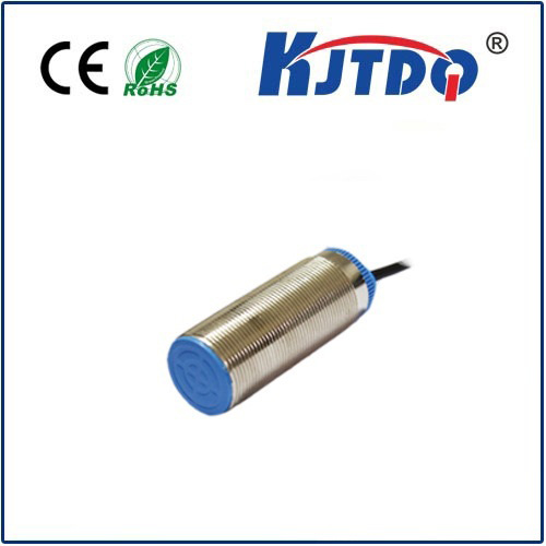
- Housing Style & Size: Cylindrical (e.g., M8, M12, M18, M30 threads) or block/rectangular shapes, chosen based on space constraints and mounting needs.
- Environmental Rating: Look for IP67 (protected against temporary immersion) or IP68/IP69K as minimums for demanding industrial settings involving washdowns, coolants, or dust.
Typical Applications Where PNP Inductive Sensors Shine
The ruggedness, reliability, and straightforward interface of PNP inductive proximity sensors make them indispensable across countless industries:
- Position Verification: Confirming cylinders are retracted/extended, detecting end-of-travel positions on slides or arms. Critical for machine sequence control.
- Object Detection & Counting: Detecting metallic parts on conveyors, counting bottles via metal caps, or checking for the presence of machined components. Essential for production monitoring and automation flow.
- Speed Monitoring: Counting gear teeth or detecting passing bolts/shafts on rotating machinery. Enables RPM calculation and overspeed protection.
- Level Detection: Sensing metal surfaces in tanks (e.g., float mechanisms) or detecting full/empty positions in metal containers. Simplifies fluid management.
- Machine Safety: Used as part of interlock circuits (e.g., confirming guards are closed) when combined appropriately with safety relays/PLCs.
Installation Tips
- Ensure sufficient clearance around the sensor head. Metal objects other than the intended target within the specified lateral or axial distance can interfere with operation or reduce the effective sensing range.
- Securely tighten mounting nuts to prevent vibration from loosening the sensor.
- Pay strict attention to wiring: Brown to +24V, Blue to 0V/Common, Black to the load (e.g., PLC input). Reversing Brown and Blue typically damages the sensor.
- Use shielded cables in electrically noisy environments and ground the shield properly at the controller end.
- Consider using flush-mountable sensors if installation requires embedding in metal; non-flush sensors require a non-metallic surround zone.
The PNP inductive proximity sensor’s combination of robust construction, non-contact sensing, simple sourcing output, and excellent compatibility with industrial controllers like PLCs solidifies its role as a foundational component in modern automation. Its ability to reliably detect metallic objects in demanding conditions


