inductive proximity sensor with arduino
- time:2025-07-10 01:38:18
- Click:0
Detect Metal Objects Seamlessly: Using Inductive Proximity Sensors with Arduino
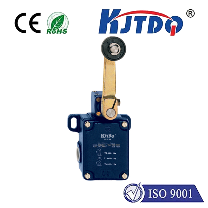
Imagine a machine arm knowing exactly where a metal part is positioned, or a conveyor belt automatically counting metallic items, all without any physical touch. This magic, fundamental to modern automation, often relies on a simple yet robust component: the inductive proximity sensor. Paired with the versatile brains of an Arduino microcontroller, these sensors become incredibly accessible for hobbyists, students, and engineers prototyping industrial solutions. This guide dives into how inductive sensors work and provides a clear path to integrating them with your Arduino projects for reliable non-contact metal detection.
Unveiling the Inductive Proximity Sensor: No Touch Required
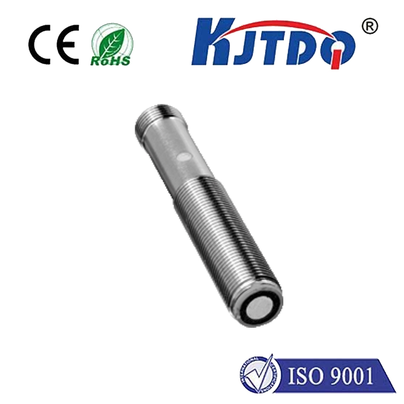
Unlike buttons or mechanical switches, inductive proximity sensors operate on a fascinating principle: electromagnetic induction. At their core lies an oscillator generating a high-frequency electromagnetic field emanating from the sensor’s active face.
When a ferrous metal target (like iron or steel) or, depending on the sensor type, non-ferrous metals (like aluminum or copper) enters this field, eddy currents are induced within the metal object. These eddy currents create their own opposing magnetic field, effectively damping the oscillation in the sensor’s coil.
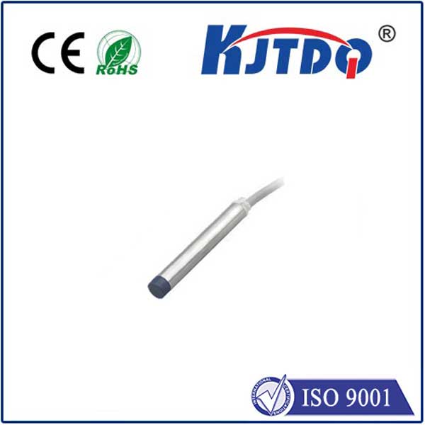
An internal circuit precisely monitors this oscillation amplitude. When the damping effect caused by a nearby metal object exceeds a preset threshold, the sensor triggers its output signal. This provides a clean, digital HIGH or LOW signal or, in specific sensor types, can modulate analog output. Crucially, this detection happens without any physical contact, making these sensors exceptionally durable and reliable in dirty, wet, or oily environments where mechanical contacts would fail. They excel at detecting metal objects through non-metallic barriers like thin plastic or wood.

Why Pair Inductive Sensors with Arduino?
- Bridging Worlds: Inductive sensors are industrial workhorses. Arduino brings the power of programmable intelligence to easily interpret the sensor signal and trigger complex actions.
- Accessibility & Cost: Arduino boards are affordable and widely available, making industrial-grade sensing technology accessible for prototyping, education, and DIY projects.
- Simplicity: Reading the digital output of a common inductive sensor (especially NPN or PNP types) is fundamentally straightforward with Arduino, involving just a single digital input pin.
- Versatility: Once the sensor signal is read by the Arduino, the possibilities explode: activating relays, controlling motors, sending data over serial/USB, updating displays, logging data to SD cards, or triggering networked events via Wi-Fi/Ethernet shields.
Getting Started: Components You’ll Need
- Arduino Board: An Arduino Uno or Arduino Nano are perfect starting points.
- Inductive Proximity Sensor: Choose a sensor suitable for your target and power requirements. Common choices are 12-24V DC powered, 3-wire types (Brown = V+, Blue = V-, Black = Signal) in NPN Normally Open (NO) or PNP Normally Open (NO) configurations. For Arduino’s 5V logic, ensure signal compatibility (see wiring below). Popular models include LJ12A3-4-Z/BX (NPN NO, 4mm range).
- Power Supply: For 12-24V sensors, you’ll need a suitable DC power source (like a bench supply or wall adapter). The Arduino’s 5V pin generally cannot power these sensors directly.
- Pull-up/Pull-down Resistor: Typically a 10k Ohm resistor might be needed depending on your sensor type and wiring. Crucial for reliable signal reading!
- Breadboard and Jumper Wires: For easy prototyping and connections.
Wiring it Up: Connecting Sensor to Arduino
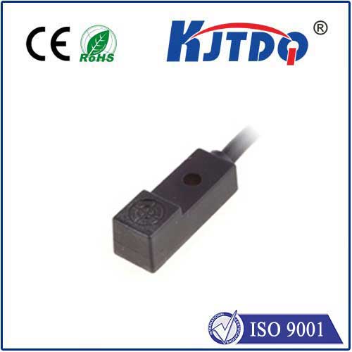
Understanding the sensor type (PNP vs NPN) and its switching state (Normally Open / Normally Closed) is critical. Let’s focus on the very common NPN Normally Open (NO) configuration:
- Sensor Power:
- Connect the sensor’s Brown wire to the positive terminal (+) of your 12-24V DC power supply.
- Connect the sensor’s Blue wire to the negative terminal (-) of your 12-24V DC power supply and also to the Arduino’s
GND
pin. This establishes a common ground reference.
- Sensor Signal (NPN NO):
- The sensor’s Black wire is the output signal. For an NPN transistor output configured as Normally Open (NO):
- When NO target detected: The output transistor is OFF. The black wire is effectively floating/disconnected.
- WHEN target detected: The output transistor turns ON, connecting the black wire internally to the sensor’s V- (Blue wire).
- To read this reliably with Arduino (which expects a defined HIGH or LOW voltage on its input pins):
- Connect a 10k Ohm pull-up resistor between the sensor’s Black (signal) wire and the Arduino’s 5V pin.
- Connect the sensor’s Black (signal) wire directly to an Arduino digital input pin (e.g.,
D2
).
- How the Signal Works (NPN with Pull-up):
- No Target: Output transistor OFF. The pull-up resistor pulls the Arduino pin
HIGH
(≈5V). Arduino reads HIGH
.
- Target Detected: Output transistor ON. This connects the signal line (Black wire) to GND (Blue wire). This overpowers the weak pull-up resistor, pulling the Arduino pin
LOW
(≈0V). Arduino reads LOW
.
- PNP Sensors (Concept): Wiring differs. A PNP NO sensor pulls the signal line HIGH when a target is detected. You would typically use a pull-down resistor (10k to GND) on the Arduino input pin. Always consult your specific sensor’s datasheet!
The Arduino Sketch: Reading the Sensor State
Here’s a fundamental code example (sketch.ino
) to read an NPN NO sensor wired as described above (with pull-up, signal on D2
):
”`arduino
// Define the pin connected to the sensor’s signal wire
const int sensorPin = 2; // Digital pin D2
void setup() {
Serial.begin(9600); // Start serial communication for monitoring
pinMode(sensorPin, INPUT); // Set sensor pin as input
Serial.println(“Inductive Sensor Monitoring Started…”);
}
void loop() {
// Read the state of the sensor pin
int sensorState = digitalRead(sensorPin);
// Interpret the state (Remember: Pull-up wiring means LOW = detected)
if (sensorState == LOW) {
Serial.println(“Metal Target DETECTED!”);
// Add actions here when target detected: turn on LED, activate relay, etc.
} else {
Serial.println(“No