npn no proximity sensor
- time:2025-07-08 00:14:11
- Click:0
NPN Proximity Sensor Not Detecting? Your Systematic Troubleshooting Guide
That sinking feeling hits the production floor: a critical machine halts. Diagnostics point to an NPN proximity sensor stubbornly reporting “nothing here” when an object is clearly present. “No proximity sensor” detection, despite the sensor being physically installed and powered, is a frustratingly common industrial hiccup. Don’t jump to replacements just yet! Often, the culprit is a misconfiguration, wiring glitch, or environmental factor easily remedied. This guide arms you with the knowledge to systematically diagnose and resolve NPN sensor failures, getting your line back to full speed efficiently.
Understanding the NPN Proximity Sensor
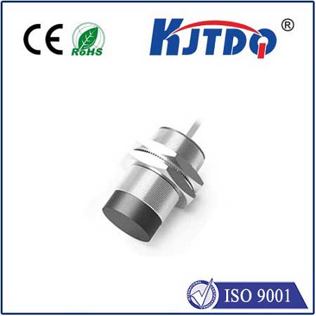
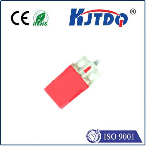
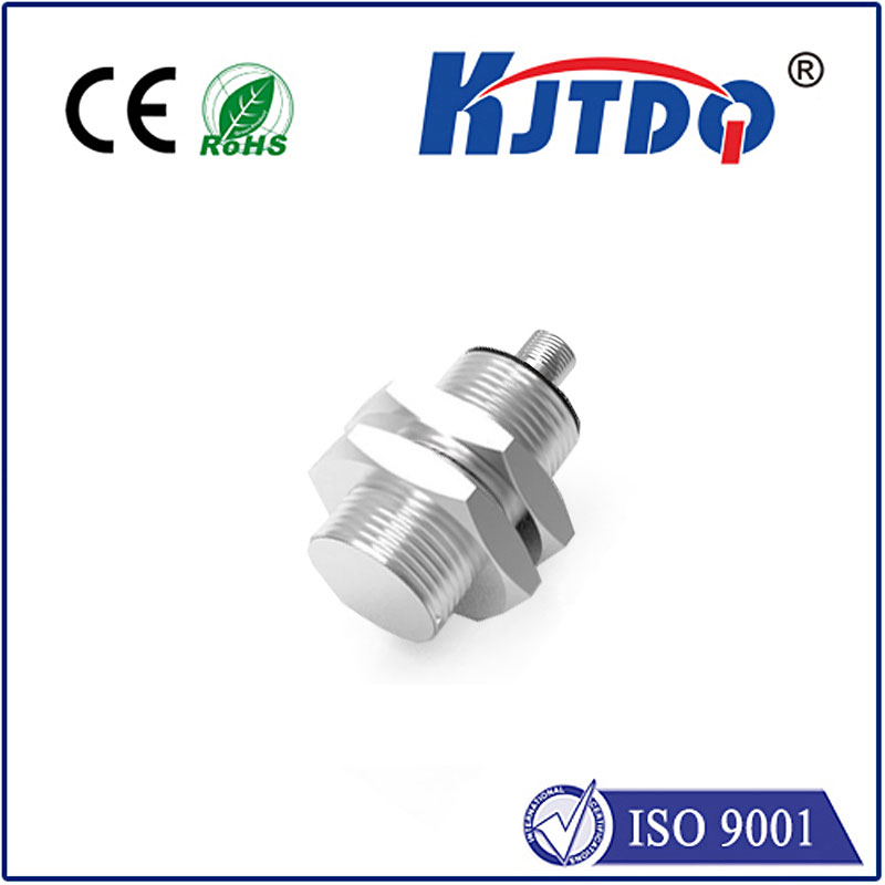
NPN proximity sensors are widely used workhorses in automation, favored for their compatibility with many PLCs (Programmable Logic Controllers). They detect the presence or absence of metallic (or sometimes non-metallic, depending on type) objects without physical contact, using electromagnetic fields.

- NPN Output Explained: Crucially, NPN signifies the type of transistor output. In an NPN sensor configured as normally open (NO):
- When no target is detected, the output transistor is OFF. The output signal wire effectively acts like an open circuit (high impedance).
- When a target is detected, the internal transistor turns ON, sinking current. This connects the output signal wire internally to the sensor’s negative (0V) wire, pulling the signal voltage down to near 0V (LOW state) relative to the common positive.
Common Reasons Why Your NPN Sensor Shows “No Detection”
When an NPN sensor fails to detect a valid target, look for these frequent offenders:
- Power Supply Issues:
- Incorrect Voltage: Is the sensor receiving voltage within its specified range (e.g., 10-30V DC)? Too low prevents operation; too high damages the sensor.
- Incorrect Polarity: Accidentally reversing positive (+) and negative (-) supply wires is a common mistake. Most sensors have reverse polarity protection but will not function.
- Voltage Drop: Long cable runs, undersized wires, or poor connections can cause significant voltage drop, leaving the sensor with insufficient operating voltage at its terminals. Measure voltage directly at the sensor’s terminals while operational.
- Unstable/Poor Quality Power: Electrical noise or ripple on the DC supply line can disrupt sensor operation.
- Wiring Faults:
- Open Circuits: Broken wires, loose connections in terminal blocks or connectors (especially on vibration-prone machines), or damaged cables prevent power or signal transmission.
- Short Circuits: Wires pinched or insulation worn through, causing unintended connections (e.g., signal wire shorted to 0V or 24V).
- Incorrect Wiring to Load/PLC: Confusing NPN and PNP wiring is prevalent. Remember, an NPN sinking output requires the load (like a PLC input) to be connected between the sensor’s output signal wire and the positive supply (+V). The PLC input provides the sourcing current that the NPN sensor sinks when active.
- Sensor Configuration & Setup:
- Incorrect Sensing Distance: Is the target entering the sensor’s effective sensing range (Sn)? Remember, the rated sensing distance is for ideal conditions; reduce it significantly in real-world use. Factors like target material, size, shape, and mounting conditions affect actual range.
- Misaligned Sensor: Ensure the sensor is perpendicular to the target path and precisely positioned. Even slight misalignment can drastically reduce range.
- Wrong Sensor Type: Using an inductive sensor on non-metallic targets, or a capacitive sensor where environmental factors (humidity, dust) cause false triggers or inhibit detection. Double-check the sensor’s specifications for suitable target materials.
- Dirty Lens/Detection Face: Accumulated dirt, grease, or metal shavings on the face of an inductive or optical sensor can block the field/lens, preventing detection. Clean the sensor face regularly.
- Load/PLC Input Issues:
- Incompatible Input Type: Verify the PLC or device receiving the sensor signal is configured for and compatible with an NPN (sinking) input. Connecting an NPN sensor to a sourcing input will not work.
- PLC Input Fault: The problem might lie with the PLC input card itself or its configuration (e.g., faulty channel, incorrect input filtering settings).
- Environmental Factors:
- Excessive Vibration/Shock: Can loosen connections, damage internal components, or momentarily move the target out of range.
- Temperature Extremes: Operating outside the sensor’s specified temperature range can cause malfunction or permanent damage.
- Strong Electrical Noise: Sources like large motors, welding equipment, or variable frequency drives (VFDs) nearby can induce electrical noise on sensor wiring, causing erratic behavior or complete failure. Proper shielding and grounding are essential.
- Chemical Exposure/Coolant: Harsh chemicals or conductive coolants can corrode connections or damage the sensor housing/seals.
Systematic Troubleshooting Steps for Your “No Proximity” NPN Sensor
Follow this logical sequence to pinpoint the issue:
- Visual Inspection: Check for obvious physical damage to the sensor, cable, or connector. Look for loose wires, cuts, pinches, or contamination on the sensing face.
- Verify Power Supply:
- Use a multimeter to measure DC voltage directly at the sensor’s power terminals (Brown/+V and Blue/0V). Ensure it’s within the sensor’s rated range and polarity is correct.
- If voltage is low, trace back towards the power source checking connections and wire size.
- Check Wiring & Connections:
- Confirm wiring against the sensor’s datasheet diagram. Triple-check polarity and the output wire (usually Black) connection. Is it wired correctly to the PLC/load input?
- Ensure all terminal screws are tight. Wiggle wires gently near connections while monitoring the sensor state or PLC input status for intermittent behavior.
- Isolate the Sensor:
- Temporary Bypass Test: If possible, temporarily connect a known-good NPN sensor (or use a simple switch) wired identically into the same circuit. If the new sensor/switch works, the original sensor is likely faulty.
- Test Sensor Directly: If feasible, power the sensor directly from a known-good bench power supply (correct voltage). Use a multimeter set to DC voltage between the Black (output) and Blue (0V) wires. When you bring a valid target into range, the voltage should drop from near the supply voltage (e.g., 24V) to near 0V. If it doesn’t, the sensor is faulty.
- Verify Load/PLC Input:
- Test the PLC input channel using a different, known-working sensor or manually forcing the input (consult PLC manual). If the input doesn’t react, the issue is likely with the PLC input card or wiring downstream of the sensor.
- Check PLC input configuration and diagnostics.
- Assess Environment & Setup:
- Measure the actual gap between the sensor face and the target. Is it less than ~50-80% of the sensor’s rated distance (Sn)? Adjust if necessary.
- Ensure the target material and size are suitable. Check alignment meticulously.
- Evaluate the environment: temperature, vibration levels, presence of dust/mist/chemicals, proximity to strong EMI sources. Consider relocating the sensor, adding shielding, or using a more robust sensor type if environmental factors are overwhelming.
Preventative Maintenance is Key
Minimize future “no proximity sensor” failures by implementing simple practices: Regularly clean sensor faces, periodically check wiring connections for tightness and corrosion, and verify sensing distances haven’t drifted due to mechanical wear. Choosing sensors with appropriate ingress


