ir proximity sensor arduino
- time:2025-07-07 15:10:17
- Click:0
IR Proximity Sensors and Arduino: Your Guide to Simple Distance Detection
Imagine teaching your Arduino projects to “see” obstacles or detect the presence of objects nearby. Sounds complex? With Infrared (IR) proximity sensors, it’s surprisingly accessible and affordable! These small, versatile components provide a fundamental sense of distance or object detection, opening doors for countless robotics, automation, and interactive projects. This guide explores the world of IR proximity sensors, demystifies their connection to Arduino, and shows you how to integrate them into your creations.
Understanding the IR Proximity Sensor
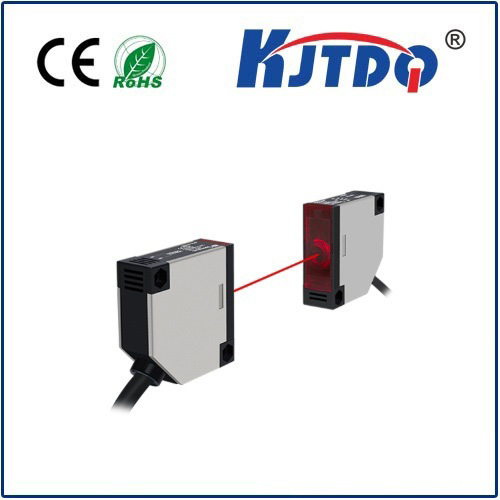
At its core, an IR proximity sensor is a simple electronic device. It contains an infrared LED emitter and an IR photodiode or phototransistor receiver, typically housed together. Here’s the clever bit:
- Emission: The IR LED constantly emits pulses of invisible infrared light.
- Reflection: If an object is present within the sensor’s detection range, this IR light reflects off its surface.
- Detection: The receiver picks up this reflected IR light. The closer the object, the stronger the reflected signal that reaches the receiver.
- Output: The sensor processes this received signal intensity. Most common digital output sensors provide a simple HIGH/LOW (or 1⁄0) signal: LOW when an object is detected within its range, and HIGH when no object is present. Analog output sensors provide a voltage proportional to the reflected IR intensity, offering more nuanced distance information (within limits).
Why Choose an IR Proximity Sensor for Arduino?
- Simplicity: Easy to understand, use, and wire.
- Low Cost: Among the most affordable sensing options.
- Low Power: Ideal for battery-powered Arduino projects.
- Ease of Integration: Generally requires minimal external components.
- Decent Performance (for Short Range): Perfect for close-proximity detection tasks (typically 2cm to 30cm, depending on the model and object reflectivity).
- Works in Darkness: Relies on its own IR light source, unaffected by ambient light conditions.
Connecting an IR Proximity Sensor to Arduino

Most commonly used digital output IR proximity sensors have three pins:
- VCC: Connect to Arduino’s 5V power pin.
- GND: Connect to Arduino’s GND.
- OUT (or Signal): Connect to any digital input pin on the Arduino (e.g., D2, D3, D4…). For analog sensors, connect the OUT pin to an analog input pin (A0, A1, A2…).
A Simple Arduino Sketch for Digital Sensors
Let’s write basic code to read a digital IR sensor connected to pin 2 and turn on the Arduino’s built-in LED (pin 13) when an object is detected:
#define sensorPin 2 // Connect sensor OUT to DIGITAL pin 2
#define ledPin 13   // Built-in LED
void setup() {
pinMode(sensorPin, INPUT); // Set sensor pin as INPUT
pinMode(ledPin, OUTPUT);  // Set LED pin as OUTPUT
Serial.begin(9600);       // Optional: For debugging
}
void loop() {
int sensorState = digitalRead(sensorPin); // Read sensor state
// Most sensors output LOW when object detected
if (sensorState == LOW) {
digitalWrite(ledPin, HIGH); // Turn LED ON
Serial.println("Object Detected!");
} else {
digitalWrite(ledPin, LOW);  // Turn LED OFF
Serial.println("No Object");
}
delay(100); // Small delay for stability
}
How This Code Works:
#define: Creates easy-to-remember names for the pins.setup(): Configures the sensor pin as an input (since we’re reading its signal) and the LED pin as an output. Starts serial communication (optional for seeing output on the Serial Monitor).loop():
digitalRead(sensorPin): Checks the voltage level on the sensor’s OUT pin. LOW (0V) typically means object detected. HIGH (~5V) means no object.if (sensorState == LOW): If an object is detected…- Turn the built-in LED ON (
digitalWrite(ledPin, HIGH)).
- Print “Object Detected!” to the Serial Monitor.
else: If no object is detected…- Turn the LED OFF (
digitalWrite(ledPin, LOW)).
- Print “No Object”.
- A small
delay(100) prevents reading the sensor too rapidly.
Key Considerations and Limitations
While incredibly useful, IR proximity sensors have inherent characteristics to keep in mind:
- Short Range: Primarily effective for close-proximity detection. Don’t expect meters of range.
- Limited Precision: While capable of rough distance estimation, they are not high-precision rangefinders. Reflected intensity depends heavily on the surface color and material. A white object will reflect much better than a black one at the same distance. They are best for threshold-based detection (“Is something closer than X cm?”) rather than exact distance measurement.
- Environmental Interference: Strong sources of infrared light (like bright sunlight or incandescent bulbs) can saturate the receiver and cause false readings or reduced detection range. Some sensors have modulation/demodulation to mitigate this.
- Analog vs. Digital: Analog sensors provide more information (a varying voltage), but interpreting that into a meaningful distance requires calibration and is still subject to surface reflectivity. Digital sensors provide simple on/off detection based on a pre-set threshold.
Practical Applications Using Arduino
The combination of IR proximity sensors and Arduino is incredibly versatile:
- Basic Robot Obstacle Avoidance: Mount sensors on the front/sides of a small robot. When the sensor triggers (LOW), tell the motors to reverse or turn.
- Object Presence Detection: Detect if a product is on a conveyor belt line, if a person is near a device, or if a drawer/cabinet is open or closed.
- Simple Counting: Count objects passing by on a line (requires careful sensor placement and object spacing).
- Interactive Installations: Trigger lights, sounds, or animations when a hand or object approaches a specific point.
- Touchless Switches: Create buttons or switches activated by a hand wave.
- Paper Level Detection: In printers or dispensers.
- Liquid Level Sensing (Translucent Containers): Detect the presence of liquid by reflection at the container wall.
Making the Most of Your Sensor
- Consult the Datasheet: Always find the datasheet for your specific sensor model. It will tell you its nominal detection range, operating voltage, pinout, output type (digital/analog), and any special considerations (like needing a pull-up resistor – most modern modules have this built-in).
- Adjustment Potentiometer: Many digital IR modules have a small blue potentiometer. Turning this adjusts the detection range threshold. Power up your circuit, place an object at the distance you want detection to occur, and slowly turn the pot until the sensor’s status LED (if present) changes state.
- Calibration (Analog Sensors): For analog sensors, you’ll need to read the
analogRead() value at known distances (and ideally on the target object surface) to map the sensor reading to an estimated distance. Remember the surface reflectivity caveat!
- Debouncing: While less critical than switches, rapid triggering can sometimes occur. Adding a small delay in your loop