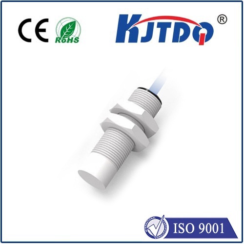
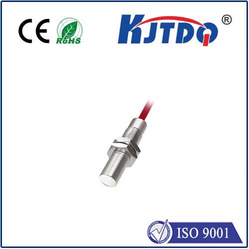
eddy current proximity sensor
- time:2025-07-04 02:24:48
- Click:0
Eddy Current Proximity Sensors: The Non-Contact Detection Powerhouse
Imagine a high-speed production line where robotic arms maneuver with millimeter precision, or a jet engine turbine spinning at tens of thousands of RPM. In such demanding environments, traditional contact-based sensors simply fail. What you need is reliability, resilience, and supreme accuracy – all delivered without physical touch. This is precisely the domain where eddy current proximity sensors excel, becoming indispensable tools across critical industries.
Understanding the Core: How Eddy Current Sensors Work
The fundamental principle behind an eddy current proximity sensor is electromagnetic induction, specifically Faraday’s Law of Induction. Here’s the breakdown:
- The Probe (Sensor Head): This contains a coil of fine wire energized by a high-frequency alternating current (AC) from the oscillator circuit within the sensor’s electronics.
- Generating the Field: The energized coil produces a rapidly alternating magnetic field that projects outward from the sensor face.
- Inducing Eddy Currents: When a conductive target material (like metals such as steel, aluminum, copper, brass, etc.) enters this magnetic field, the changing flux induces swirling circular electrical currents within the target material. These are the eddy currents.
- Energy Absorption & Field Disturbance: The flow of these eddy currents consumes energy. This energy loss manifests as a change in the impedance (resistance to AC flow) of the sensor coil itself. Critically, the eddy currents also generate their own opposing magnetic field, which interacts with the original field from the sensor coil.
- Detecting the Change: The sensor’s electronic circuitry is finely tuned to detect this change in the coil’s impedance (primarily its resistance and inductive reactance). The magnitude of this change is directly proportional to the distance between the sensor face and the target – the closer the target, the stronger the eddy currents and the larger the impedance shift.
- Signal Processing & Output: The electronics process this impedance change and convert it into a usable output signal. This is typically a scaled DC voltage (e.g., 0-10V), current (e.g., 4-20mA), or a simple digital ON/OFF switch (PNP/NPN).
Key Advantages of Eddy Current Technology:

- True Non-Contact Operation: Absolutely no physical wear on the sensor or the target, enabling infinite lifespan in ideal conditions and measurement of fragile or sensitive objects.
- High Resolution and Accuracy: Capable of detecting minute position changes – resolutions down to microns (µm) are achievable with high-end models, making them ideal for precision metrology and position measurement.
- Robustness: Immune to dust, dirt, oil, water vapor, non-conductive contaminants, and high-pressure washdowns. The sensing face is usually solid (no openings), making them inherently sealed. This resilience is crucial in harsh industrial environments like foundries, machine shops, and food processing.
- High-Speed Response: Can track very rapid movements or vibrations (kHz ranges) due to the underlying electromagnetic principle, unlike optical sensors that might struggle with reflective surfaces.
- Temperature Tolerance: Function reliably across wide temperature ranges (many models from -40°C to +200°C), suitable for applications near furnaces, engines, or cryogenic processes.
- Target Material Sensitivity: While primarily designed for conductive metals, the sensing range and behavior vary significantly based on the target’s conductivity and magnetic permeability (ferrous vs. non-ferrous). Calibration for the specific target material is often essential.
Where Eddy Current Sensors Shine: Core Applications
Their unique capabilities make eddy current sensors vital in numerous sectors:
- Industrial Automation & Machinery:
- Precise position feedback for hydraulic/pneumatic cylinders (replacing LVDTs).
- Vibration monitoring of shafts, bearings, and turbines in predictive maintenance systems, detecting imbalance or bearing wear early.
- Rotor position sensing in high-speed electric motors.
- End-of-travel detection for moving parts.
- Runout and eccentricity measurement on rotating shafts.
- Monitoring thickness of metal sheets, foils, or coatings (using differential measurement with two sensors).
- Automotive & Aerospace:
- Brake pad wear sensing (detecting distance to the brake disc).
- Suspension travel measurement.
- Valve timing and position in engines.
- Thrust measurement and clearance control in jet engines (monitoring blade tip clearance).
- Landing gear position confirmation.
- Power Generation:
- Vibration analysis for generators and large turbines.
- Shaft speed and position sensing.
- Monitoring steam/gas turbine blade health and clearance.
- Metalworking & Material Sciences:
- Material sorting based on conductivity/permeability.
- Non-destructive testing (NDT) detecting surface cracks or material inconsistencies near the surface.
- Precision machining feedback for grinding, milling, and EDM processes.
Critical Considerations: Material & Calibration
A defining characteristic, and sometimes a limitation, is their sensitivity to the electromagnetic properties of the target. The sensing range depends heavily on:
- Conductivity: Higher conductivity metals (like copper, aluminum) generally induce stronger eddy currents than lower conductivity metals (like titanium, some steels).
- Permeability: Ferromagnetic materials (like iron, steel) exhibit both conductivity and permeability effects, typically allowing for longer sensing ranges compared to non-ferromagnetic conductors of similar conductivity (like aluminum, brass).
Therefore, the sensor must be calibrated or specified for the exact target material it will sense in the application. Using a sensor calibrated for mild steel to sense aluminum will result in a significantly reduced effective range. Most reputable manufacturers provide calibration data and correction factors for common materials.
Comparing Strengths: Eddy Current in Context
| Feature |
Eddy Current Sensor |
Inductive Sensor (Standard) |
Capacitive Sensor |
Optical Sensor |
| Target Requirement |
Conductive Metal |
Ferrous Metal |
Any Material |
Opaque/Reflective Surface |
| Non-Contact? |
Yes |
Yes |
Yes |
Yes |
| Affected by… |
Target EM Properties |
Target EM Properties |
Dielectric Constant, Humidity |
Light, Dirt, Steam, Reflectivity |
| Harsh Environment Suitability |
Excellent (Immune to dirt, dust, oil, non-conductive fluids) |
Very Good |
Moderate (Affected by coatings) |
Poor (Affected by obscurants) |
| Resolution/Accuracy |
Excellent (Micron Level Possible) |
Good |
Good to Excellent |
Excellent |
| Ideal Use Case |
High-precision metal position/distance in harsh settings |
Detecting presence of steel parts |
Level, thickness (non-metals, some liquids) |
Clean, controlled environments |
Choosing the Right Tool
Eddy current proximity sensors are not a universal solution. They are the specialists for high-precision, high-reliability, non-contact distance and position measurement of conductive metals, particularly where environmental challenges rule out optical or basic inductive sensors. When your application involves demanding conditions, extreme temperatures, the need for micron-level accuracy on metal targets, or robust vibration monitoring, eddy current sensors emerge as an exceptionally powerful and reliable technology. Understanding their principle of operation and material dependencies is key to unlocking their full potential and integrating them effectively


