inductive position sensor
- time:2025-07-04 00:24:13
- Click:0
Unlocking Precision Measurement: The Essential Guide to Inductive Position Sensors
Imagine needing to know the exact position of a component hurtling down a high-speed assembly line, submerged in oil, or exposed to intense vibration and debris. Contact methods fail, optical sensors fog or get dirty. What’s the solution? Inductive position sensors emerge as the unsung heroes in these demanding scenarios, offering robust, reliable, and precise measurement where others falter. This guide delves into the world of inductive sensing, explaining how they work, why they’re invaluable, and where they shine brightest.
The Core Principle: Electromagnetism in Action
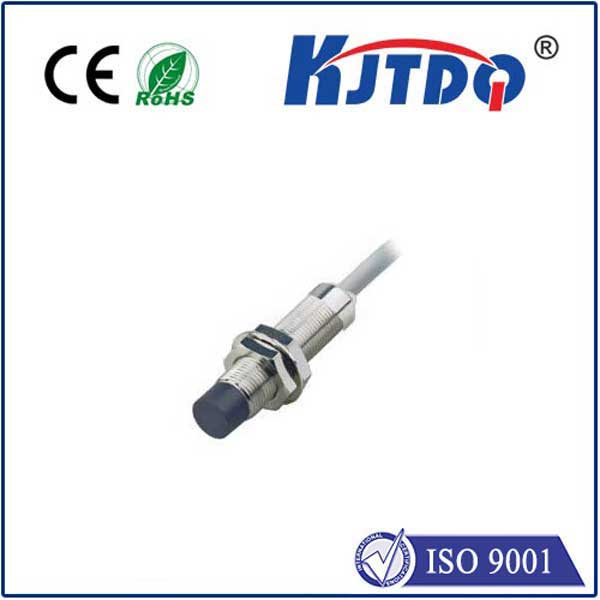
At their heart, inductive position sensors operate on fundamental principles of electromagnetism, specifically Faraday’s Law of Electromagnetic Induction. Unlike potentiometers (which rely on physical contact) or optical encoders (which require a line of sight), inductive sensors are fundamentally non-contact. They generate an oscillating electromagnetic field and detect changes induced in that field by a nearby metallic target – the object whose position is being measured. Crucially, the target does not need to be ferromagnetic; conductive materials like aluminum, copper, or brass work perfectly.
How It Works: Inside the Inductive Sensing Mechanism

- Generating the Field: A coil within the sensor, driven by an oscillator circuit, produces a high-frequency alternating magnetic field that extends into the surrounding space.
- Interaction with the Target: When a conductive target moves into this field, eddy currents are induced on its surface. These swirling currents oppose the sensor’s original magnetic field according to Lenz’s Law.
- Detecting the Change: Sophisticated circuitry within the sensor precisely monitors the change in the electromagnetic field caused by the eddy currents. This change manifests as:
- A shift in the resonant frequency of the oscillator circuit.
- A change in the amplitude of the oscillation.
- A shift in the phase angle between the excitation signal and the received signal.
- Position to Signal Conversion: The specific change detected (frequency, amplitude, or phase) is directly correlated to the distance and/or angle of the target relative to the sensor head. This change is converted into a standardized, highly accurate output signal, typically analog (e.g., 0-10V, 4-20mA) or digital (e.g., SSI, IO-Link).
- Key Insight: The strength of the eddy currents, and thus the measurable change in the field, depends critically on the distance between the sensor coil and the target. This dependence forms the basis for precise position measurement.
Why Choose Inductive Position Sensors? Unrivaled Advantages
Inductive position sensors are not just another option; they offer distinct advantages making them essential in harsh environments:
- Ruggedness and Durability: With no moving parts and no physical contact with the target, they are incredibly resistant to wear, shock, and vibration. Their lifespan dramatically exceeds contact-based sensors.
- Environmental Resilience: Sealed housings (often rated to IP67, IP68, or IP69K) make them immune to contamination – dust, oil, grease, moisture, and even high-pressure washdowns pose little threat. They function reliably where optical sensors would fail.
- Immunity to Interference: Unlike capacitive sensors, they are largely unaffected by non-conductive contaminants (oil, water film) between the sensor and target. Their electromagnetic nature also grants excellent EMI (Electromagnetic Interference) resistance, crucial in electrically noisy industrial settings.
- High Resolution and Accuracy: Modern designs offer sub-micron resolution and excellent linearity, enabling precise control in even the most demanding applications, such as semiconductor manufacturing or precision machining.
- Long Sensing Distances: Depending on the size and design, they can achieve significant sensing ranges compared to other non-contact technologies like Hall effect sensors.
- Wide Temperature Range: Engineered to operate reliably across extreme temperatures, from well below freezing to high-temperature processes.
Key Applications: Where Robust Precision is Non-Negotiable
The unique strengths of inductive sensing translate into critical roles across numerous industries:
- Industrial Automation & Robotics: Monitoring cylinder rod position in pneumatic/hydraulic actuators, verifying gripper closure, detecting end-of-arm tooling position, precise feedback in servo systems, and confirming part presence/clamping on assembly lines. Their reliability in dirty, wet, and vibrating factory floors is paramount.
- Automotive & Transportation: Measuring suspension travel, throttle position sensing (especially in harsh under-hood environments), transmission gear selection, brake pedal position, and various valve positions. EMI immunity is crucial near motors and ignition systems.
- Hydraulics & Heavy Machinery: Precise feedback on hydraulic cylinder position for excavators, cranes, presses, and agricultural equipment. Their ability to withstand high pressure, shock, and fluid immersion is essential.
- Aerospace & Defense: Monitoring landing gear position, flight control surfaces, actuation systems in engines, and other critical functions demanding ultra-high reliability in extreme conditions.
- Machine Tools & Metrology: Providing high-resolution feedback for axis positioning on CNC machines, coordinate measuring machines (CMMs), and precision grinding equipment. Immunity to coolant swarf and oil is vital.
- Specialized Variants: LVDT & RVDT: Linear Variable Differential Transformers (LVDTs) and Rotary Variable Differential Transformers (RVDTs) are sophisticated types of inductive sensors. They utilize multiple coils arranged differentially to achieve exceptionally high accuracy, linearity, and infinite resolution, making them the gold standard for demanding metrology and control applications.
Choosing the Right Sensor: Key Considerations
Selecting the optimal inductive position sensor requires careful thought:
- Measurement Type: Linear vs. Rotary (angular) displacement.
- Range: Required measurement distance or rotation angle.
- Accuracy & Resolution: Needed precision level.
- Output Signal: Compatibility with control systems (analog voltage/current? Digital protocol like IO-Link, CANopen, SSI?).
- Environmental Conditions: Temperature range, exposure to chemicals, pressure, moisture, EMI levels.
- Target Material: The sensor must be calibrated for the specific conductive material being sensed (steel, aluminum, copper, etc.).
- Mechanical Constraints: Size, mounting style (flush/non-flush?), electrical connections.
Understanding the Limits
While exceptionally robust, inductive sensors do have limitations. They only sense conductive targets – plastics, ceramics, or other non-conductors are invisible to them. Performance can be influenced by adjacent metal structures (mounting brackets, housings), requiring careful installation per the manufacturer’s guidelines. While highly immune to interference, extremely strong electromagnetic fields close to the sensor could potentially affect readings. Finally, achieving very long ranges often necessitates larger sensor heads. However, for countless applications demanding reliable, high-precision position feedback in challenging environments, the benefits of inductive position sensing overwhelmingly outweigh these constraints, solidifying their role as a cornerstone technology in modern industrial measurement and control.


