inductive position sensor
- time:2025-06-15 00:12:13
- Click:0
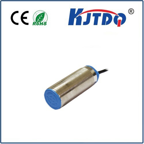
Inductive Position Sensors: Unlocking Precision in Harsh Environments Without Contact
Imagine needing to know the exact position of a component within a machine. Now, picture that machine operating in an environment filled with dust, grease, extreme temperatures, or constant vibration. Optical sensors might fog or get dirty. Potentiometers could wear out. This is where inductive position sensors emerge as a robust and highly reliable solution. These ingenious devices provide accurate, non-contact position measurement, thriving precisely where other technologies falter. They are the unseen workhorses enabling precise control and feedback in countless demanding industrial and automotive applications.
Understanding the Core Principle: Electromagnetic Induction
At the heart of every inductive position sensor lies the fundamental principle of electromagnetic induction, discovered by Michael Faraday. Simply put, when an electrical conductor moves within a changing magnetic field, an electrical current (voltage) is induced in that conductor. Conversely, a current flowing through a conductor generates a magnetic field around it.
An inductive sensor leverages this effect. It consists primarily of a coil of wire wound around a ferromagnetic core, forming an inductor. When an alternating electrical current (AC) flows through this coil, it generates a dynamic, oscillating magnetic field radiating outward from the sensor face.
How It Senses Position: The Role of the Target

The crucial element in position sensing is the target – typically a simple piece of electrically conductive metal (like steel or aluminum). As this target moves closer to or further away from the sensor’s active face, it interacts dramatically with the generated magnetic field:
- Eddy Currents: The changing magnetic field induces swirling electrical currents, known as eddy currents, within the conductive target material.
- Opposing Field: These eddy currents, in turn, generate their own magnetic field. Critically, this secondary field opposes the original field generated by the sensor coil (Lenz’s Law).
- Damping Effect: The opposing magnetic field effectively “dampens” or reduces the strength and alters the characteristics (like amplitude and sometimes phase) of the original field generated by the coil.
- Measuring the Change: This damping effect changes the electrical properties of the coil itself. Specifically, it alters the coil’s inductance (L) and also affects its effective resistance (due to losses from the eddy currents). An integrated electronic circuit continuously monitors this change – most commonly the change in amplitude or frequency of the oscillator circuit driving the coil.
The Position Link: From Electrical Change to Distance
The degree of damping is directly proportional to the distance between the sensor face and the conductive target. As the target moves closer:
- Stronger Interaction: Eddy currents are induced more readily and powerfully.
- Increased Damping: The opposing magnetic field intensifies.
- Greater Change: The oscillator’s amplitude decreases significantly (or its frequency shifts measurably).
- Linear Output: The sensor’s sophisticated electronics process this change and convert it into a highly accurate, linear analog output signal (like 4-20mA, 0-10V, or ratiometric outputs) or a precise digital signal (like PWM or SSI), which directly corresponds to the measured position or displacement.
Key Advantages Driving Adoption
The operational principle of inductive sensing confers several compelling advantages:
- Non-Contact Operation: The sensor doesn’t touch the target. This eliminates mechanical wear and tear, significantly enhancing sensor longevity and reliability.
- Robustness: With no sensitive optical components or sliding contacts, these sensors excel in harsh environments. They are inherently resistant to dust, dirt, moisture, oils, vibrations, and even high-pressure washdowns.
- Immunity to Contaminants: Grease, oil, paint splatter, and other non-conductive debris on the sensor face generally do not affect performance, unlike optical sensors.
- High Resolution & Repeatability: Modern designs offer exceptional precision and repeatability, enabling precise motion control and quality assurance.
- Speed: Capable of high-speed measurement, tracking rapid movements effectively.
- Reliability & Long Life: The simple, solid-state construction (no moving parts directly interacting) leads to high Mean Time Between Failures (MTBF) and lower maintenance requirements.
- Relatively Simple Construction: Often results in lower cost compared to technologies like resolvers or capacitive sensors in similar environmental ratings.
Common Applications: Where They Shine
The unique blend of robustness, precision, and non-contact operation makes inductive position sensors indispensable across numerous sectors:
- Industrial Automation: Monitoring hydraulic/pneumatic cylinder rod position, valve spool position, press/die height control, robotic arm joint angles, linear/rotary stage position feedback.
- Automotive Engineering: Measuring suspension travel, gearshift position, throttle valve position, brake pedal travel, clutch position, steering angle sensing (often as part of redundant systems).
- Hydraulics & Pneumatics: Feedback on actuator positions critical for closed-loop control systems within heavy machinery.
- Manufacturing Machinery: Precise positioning feedback in CNC machines (tool position, axis control), injection molding machines, packaging lines, and metal forming equipment.
- Rail & Transportation: Monitoring pantograph height, bogie position, door status sensors.
- Offshore & Heavy Industry: Position sensing in environments where corrosion, shock, and vibration are extreme.
Key Considerations in Selection and Use
While highly versatile, optimal performance requires understanding key factors:
- Target Material: Requires a conductive metal. Ferrous metals (steel, iron) yield the strongest signal and longest sensing ranges. Non-ferrous metals (aluminum, brass, copper) induce weaker eddy currents, resulting in shorter nominal sensing ranges. Sensor specification sheets always define the “factor” for different materials.
- Sensing Range: Each sensor has a specified nominal sensing range (
Sn). The effective operating range is typically 0-80% of Sn, ensuring stable linear output. Never mount targets within the sensor’s minimum operating distance.
- Target Size & Shape: For linear displacement sensors, the target must be sufficiently large to interact consistently with the sensor face throughout its travel. Shape matters; flat targets are ideal. Rotary sensors require specific target geometries.
- Output Type: Choose the appropriate analog (voltage, current) or digital (PWM, SSI, IO-Link) interface for your control system.
- Environmental Ratings: Verify IP (Ingress Protection) ratings for dust/water and temperature range suitability for the specific application environment. Look for resistance to chemicals if needed.
- Mounting & Shielding: Proper mechanical mounting is crucial for stability. Flush-mount sensors require metal backing for their magnetic field, while non-flush types can sense into their surroundings but need attention to avoid interference from adjacent metal objects (mounting brackets, etc.). Electrical shielding is vital in noisy environments.