check

check

check

check
check
check
check
check

check

check
Integrating limit switches with an Arduino CNC shield transforms hobbyist CNC machines into reliable, production-ready tools. These small but critical components act as digital sentinels, preventing damage by halting motion when the tool reaches its physical boundaries. For makers and engineers working with Arduino-based controllers like the popular CNC Shield V3, understanding how to properly wire, configure, and utilize limit switches is non-negotiable for safety and precision.
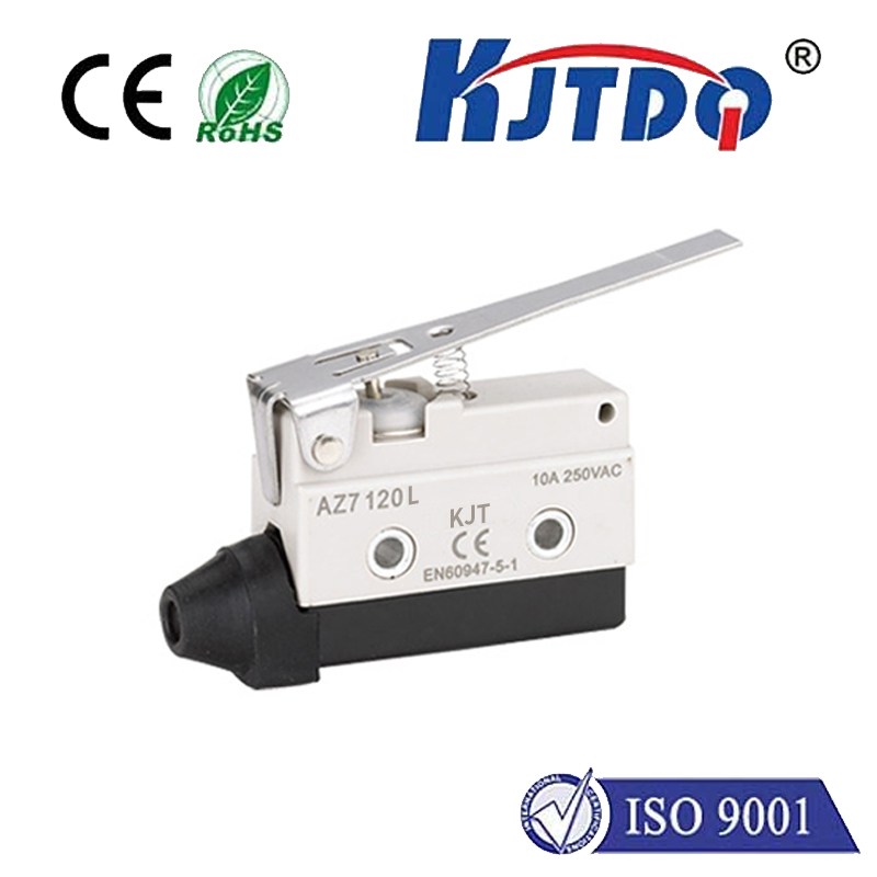
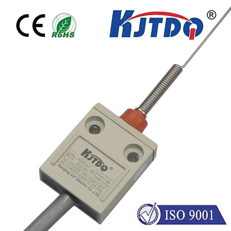
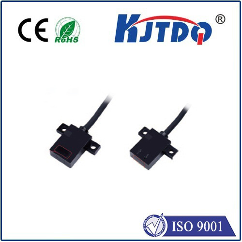
The primary function of a limit switch is to detect the presence or position of a machine part. In a CNC router or mill, switches are typically installed at the maximum travel points of each axis (X, Y, and Z). When the machine's gantry or spindle touches the switch's actuator, it triggers a signal. The Arduino, running firmware like GRBL, interprets this signal as an immediate command to stop all motion, preventing a crash that could break tools, damage the workpiece, or harm the machine's mechanical structure.
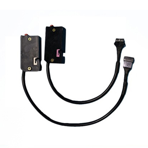
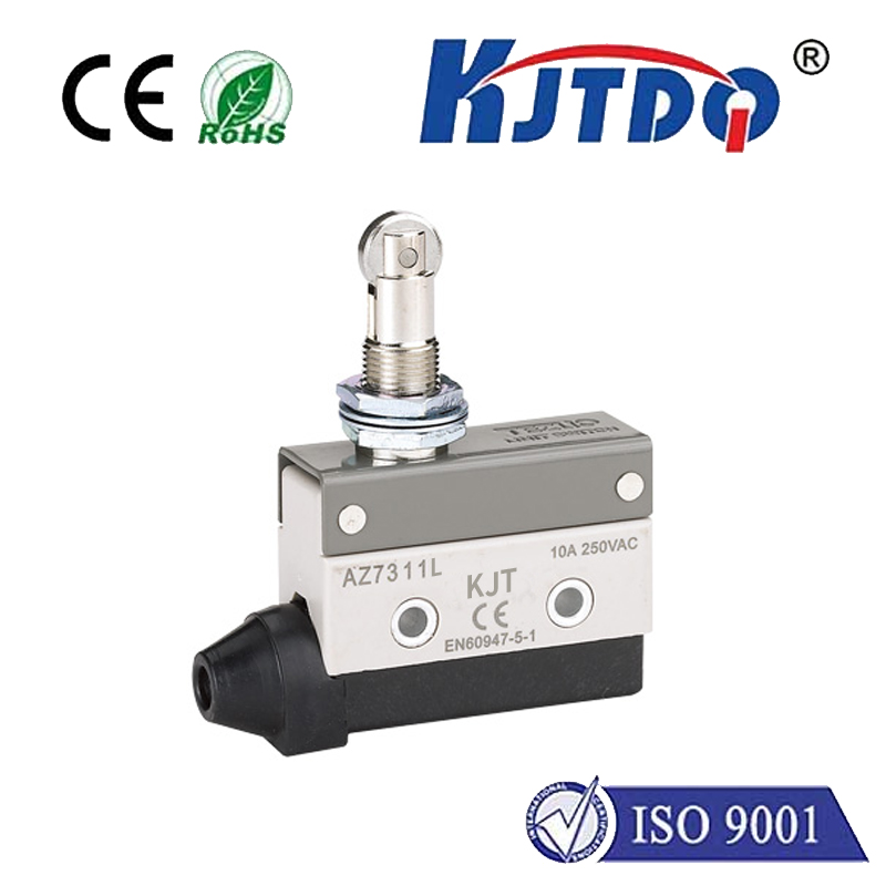
Wiring limit switches to an Arduino CNC shield is straightforward, thanks to dedicated input pins. Most shields, including the ubiquitous V3 model from Protoneer, have clearly labeled pins for X-, Y-, Z- limit signals, and often for probes. The common configuration uses a Normally Open (NO) switch setup. All switches share one common ground wire, which connects to the shield's ground pin. The signal wire from each switch then connects to its respective limit pin. It's crucial to enable the internal pull-up resistors in the GRBL configuration, so the Arduino reads a HIGH signal normally and a LOW signal when a switch is triggered, providing noise immunity.
Configuration within the GRBL firmware is the next critical step. Using a sender software like Universal GCode Sender (UGS) or Candle, you must access the GRBL settings. Key parameters involve homing and hard limits. Enabling hard limits ($21=1) allows the machine to stop immediately upon any switch trigger during operation. The homing cycle ($22=1) uses these same switches to find a precise, repeatable starting position for the machine. You must also set the homing direction and feed rate correctly for each axis to ensure the machine moves toward the switches slowly and consistently during the homing sequence.
Beyond basic crash prevention, limit switches enable automated homing. At the start of a job, a homing cycle commands the machine to move each axis until it contacts its limit switch. This establishes a known reference point (machine zero), ensuring that every cut starts from an identical position. This repeatability is vital for multi-part jobs and for resuming work after a pause. Furthermore, with switches installed, you can implement software travel limits, creating a protected workspace within the physical boundaries, adding an extra layer of safety.
Troubleshooting is a common part of the process. The most frequent issue is false triggering, often caused by electrical noise from stepper motors. This is mitigated by using shielded cables for switch wiring, keeping them away from motor power lines, and ensuring solid connections. Another common problem is the machine not stopping when a switch is pressed, which usually points to incorrect GRBL settings, faulty wiring, or a defective switch. Simple multimeter continuity tests can quickly diagnose a bad switch.
For advanced users, the same input pins can often be dual-purposed. For instance, the Z-axis limit pin can frequently be reconfigured to accept a touch probe for automated tool height setting, maximizing the functionality of the limited I/O on the Arduino board. This requires careful firmware configuration but demonstrates the flexibility of the system.
In essence, limit switches are the cornerstone of a safe and autonomous CNC system built around an Arduino. They move the machine from a manually supervised device to an automated tool capable of unattended operation with confidence. The integration process—involving careful mechanical mounting, clean electrical wiring, and precise software configuration—is a rewarding project that significantly elevates the capability, safety, and professionalism of any DIY CNC machine. Investing time in correctly implementing limit switches protects your hardware investment and ensures consistent, high-quality results in every project.