QS-II Pull rope switch
- time:2025-09-24 03:16:14
- Click:0
QS-II Pull Rope Switch: Your Critical Lifeline for Conveyor Emergency Stopping
Imagine a split-second emergency on a long conveyor line: a worker’s sleeve caught, a jam threatening catastrophic damage, or sparks flying near flammable material. Reacting instantly is paramount, but distances can be vast, and control panels unreachable. This is where the QS-II Pull Rope Switch transforms from a simple device into a vital safety lifeline. Strategically installed along conveyor routes, it provides personnel anywhere along the belt’s path with the immediate, uncompromising ability to halt operations, preventing injury and damage before tragedy strikes. Understanding its design and function is non-negotiable for robust industrial safety.
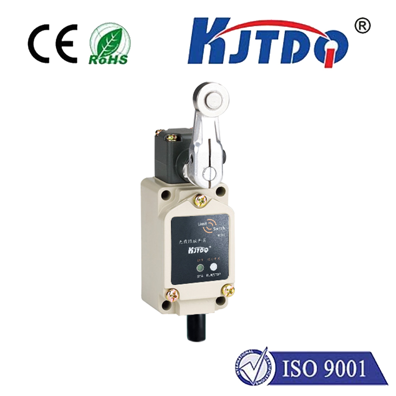
So, what exactly is a QS-II Pull Rope Switch? Fundamentally, it’s a manually activated emergency stop (E-Stop) device engineered specifically for conveyor systems and similar long machinery runs. Its core purpose is unambiguous: to provide a fast, reliable, and easily accessible means for any operator or worker within proximity to initiate a complete system shutdown when danger arises. The designation “QS-II” typically signifies a specific series or model within a manufacturer’s lineup, often indicating features like dual-circuit contacts or robust construction. The defining element is the continuous “pull rope” – a wire rope or cable installed parallel to the conveyor, within easy reach.
How the QS-II Pull Rope Switch Works: Simplicity is Safety
The operational principle is elegantly straightforward, prioritizing reliability over complexity:

- The Pull Rope: A galvanized steel wire rope runs the length of the protected conveyor section, anchored at both ends and supported at regular intervals (usually between 10-15 meters) by idler brackets to maintain proper tension and accessibility. This rope is the universal actuator.
- Tension Mechanism: The rope is kept under controlled tension. The QS-II switch housing incorporates a spring-loaded mechanism or tensioning device integral to its design.
- Activation: Applying a small amount of force (typically around 20-40 lbs or 9-18 kg) anywhere along the rope’s length increases the tension. This forceful pull directly overcomes the spring tension in the switch body.
- Mechanical Latching: Inside the robust corrosion-resistant enclosure (often aluminum, stainless steel, or high-impact plastic), the increased tension mechanically trips a latching mechanism. This latch is crucial – it ensures the switch remains firmly in the “tripped” or STOP position even after the pulling force is released.
- Electrical Contact Action: The mechanical trip forces a set of force-guided, positively driven contacts inside the switch to change state instantly. Crucially, the QS-II design typically features normally closed (NC) contacts that open upon activation, directly interrupting the safety circuit controlling the motor starter or drive.
- System Shutdown: Breaking the safety circuit automatically cuts power to the conveyor motor(s) and associated machinery, bringing everything to a safe stop.
- Manual Reset: Safety dictates that the system cannot simply restart automatically. After the emergency is resolved and the cause dealt with, a qualified operator must physically go to the specific QS-II switch housing that was tripped (usually indicated by a visual flag or position indicator). Manual reset involves twisting, turning, or pulling a lever on the switch body to release the latch and reset the contacts to their normal (closed) state, allowing the circuit to be re-energized once initiated from the control panel.
Key Features Enhancing Safety and Reliability in QS-II Pull Rope Switches:
- Dual-Circuit Contacts: Many QS-II models incorporate two completely independent contact sets (e.g., 1 NC/1 NO + 1 NC/1 NO). This redundancy allows connection to two separate safety circuits (like a control circuit and an additional monitoring circuit), significantly boosting system safety integrity.
- Robust Construction: Encased in NEMA 4/4X or IP65/IP67 rated enclosures, QS-II switches resist harsh industrial environments – dust, moisture, vibration, and corrosion are no match. Internal components are designed for shock resistance and long service life.
- Corrosion-Resistant Cable/Rope: The pull rope itself is hot-dip galvanized or stainless steel, ensuring it doesn’t degrade or seize up due to rust or chemical exposure.
- Clear Visual Indication: A brightly colored trip indicator flag or plunger clearly shows the activation status from a distance (“Normal” vs. “Tripped”), aiding in rapid identification of which section initiated the stop.
- Tension Monitoring Capability: Some advanced models can integrate with monitoring systems to alert if the rope tension falls below a safety threshold (e.g., if a bracket breaks or the rope snaps).
Why the QS-II Pull Rope Switch is Indispensable: Meeting the Standard
This device is far more than just convenient; it’s a cornerstone of compliant safety design. OSHA regulations and global safety standards (like ANSI B20.1, AS 4024.1, ISO 13850) mandate that emergency stop devices be readily accessible to personnel operating or working near machinery where hazards exist. Long conveyors inherently pose risks like entanglement, shear points, impacts, and fire hazards.
Placing traditional push-button E-Stops only at ends or control points is insufficient for a 100-meter conveyor. Without pull rope switches like the QS-II, a worker caught midway would have no way to signal for help or initiate a stop themselves, leading to potentially devastating delays in halting the machine. They effectively create a continuous emergency stopping zone along the entire length of the hazard, empowering every individual on the floor.
Implementing QS-II Pull Rope Switches Effectively:
- Strategic Placement: Install switches at regular intervals (consider conveyor speed, visibility, and access) and at key hazard points (drive heads, tail pulleys, transfer points). Follow manufacturer spacing guidelines rigorously.
- Proper Tensioning: Correct rope tension is paramount. Too loose, and the switch won’t trip reliably; too tight, and it might cause false trips or excessive wear. Use the switch’s integrated tensioner or follow installation instructions precisely.
- Secure Mounting: Brackets must be robustly fixed to solid structures, not just conveyor frames subject to vibration.
- Wiring Integrity: Connect using appropriate safety-rated cables and terminals. The NC contacts must break the safety circuit powering the conveyor motor controls. Ensure the circuit wiring is fault-tolerant where required by safety level (e.g., Cat 3⁄4 per ISO 13849).
- Regular Testing and Inspection: Schedule frequent, documented functional tests where personnel deliberately pull the rope to verify the conveyor stops and the switch latches/resets correctly. Inspect the rope for kinks, corrosion, or damage, and check enclosures and brackets.
Beyond Conveyors: Versatile Protection
While the primary application is belt conveyors, the QS-II Pull Rope Switch principle applies wherever long stretches of machinery pose access issues or entanglement risks:
- Roller Conveyors
- Assembly Lines
- Material Handling Systems
- Processing Lines (Food, Chemical, Packaging)
- Automated Warehouse Systems
**Investing in the Lifeline: The QS-II Pull Rope Switch delivers an unparalleled combination of immediate accessibility, mechanical reliability, and robust construction. By integrating these critical devices according to best practices and


