check

check

check
check
check
check
check
check
check
check
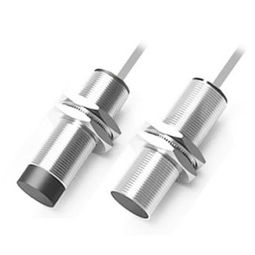
Picture an automotive assembly line: robots whirring, components gliding into place with uncanny precision. Hidden heroes ensuring this seamless operation are countless proximity sensors, silently detecting metal parts without physical contact. Among the most prevalent and versatile types is the 3-wire proximity sensor, a fundamental building block in automation, robotics, and machinery. Its distinct wiring sets it apart, offering enhanced performance and reliability compared to simpler models. This article cuts through the complexity, explaining how these ubiquitous sensors work, why their wiring matters, and how to implement them effectively. Understanding the 3-wire configuration is crucial for engineers, technicians, and anyone navigating modern industrial landscapes.
The Core Principle: Non-Contact Detection
Like all proximity sensors, the 3-wire variant operates on the principle of non-contact detection. Most commonly, they are inductive sensors, generating an oscillating electromagnetic field from their active face. When a metallic target (like a machine part, piston, or gear tooth) enters this field, it disrupts the oscillations. The sensor’s internal circuitry detects this change and triggers an output signal. Alternative technologies exist (capacitive, photoelectric), but inductive dominates metal detection applications. The key advantage? No wear and tear from physical contact, translating to long service life and minimal maintenance.
Why Three Wires? Moving Beyond Simplicity
Simpler 2-wire sensors integrate directly into the power circuit. While cost-effective, they have limitations: lower current-carrying capacity, voltage drop issues affecting reliability, and sometimes slower switching speeds. The 3-wire proximity sensor solves these problems by separating the power supply from the output signal:
This separation is crucial. The sensor’s internal electronics draw their operating power reliably from Brown and Blue, independent of the load connected to the Black output wire. This ensures stable operation even when switching loads like relays, PLC inputs, or indicator lamps.
The Critical Distinction: NPN vs. PNP Outputs
The behavior of the Black output wire defines the two fundamental types of 3-wire proximity sensors: NPN and PNP. This choice depends entirely on your control circuit’s requirements.
PNP Proximity Sensor (Sourcing Output):

When a target is detected, the internal electronic switch closes between the Black (output) wire and the Brown (positive) wire.
Essentially, the sensor sources positive voltage (+V) to the load connected to the Black wire.
Think: “Positive when Present”.
Common configuration in Europe and often preferred when connecting directly to PLC inputs looking for a positive voltage signal.
NPN Proximity Sensor (Sinking Output):
When a target is detected, the internal electronic switch closes between the Black (output) wire and the Blue (negative/ground) wire.
Essentially, the sensor sinks current to ground through the Black wire.
Think: “Switches Negative when Present”.
Common configuration in Asia and North America. Often used when the load needs to be connected between the positive supply and the sensor output.
| Feature | PNP Sensor (Sourcing) | NPN Sensor (Sinking) |
|---|---|---|
| Output State | Switches +V when ON | Switches GND when ON |
| Load Connect | Load between Output & GND | Load between +V & Output |
| Schematic | ||
| Mnemonic | Positive when Present | Switches Negative |
| PLC Common | Often used with Sinking PLC | Often used with Sourcing PLC |
| Region | Widely used in Europe | Common in Asia & North America |
Connecting it Right: Basic Wiring for 3-Wire Sensors
Proper wiring is paramount for reliable operation. Here’s the fundamental connection scheme for both types:
For a PNP Sensor: Connect the other side of the load to the Blue wire (0V/GND).
For an NPN Sensor: Connect the other side of the load to the Brown wire (+V).
Always, always consult the sensor’s datasheet for its specific voltage range, output current rating, and connection diagram. Exceeding limits causes failure.
Ensure secure connections and use appropriate cable types for your environment (e.g., shielded cable in electrically noisy areas).
Key Advantages Driving Widespread Use
The popularity of the 3-wire proximity sensor isn’t accidental. Its design offers tangible benefits:
Implementation Tips and Tricks
Selecting and using a 3-wire proximity sensor effectively involves more than just wiring: