mpcnc limit switch
- time:2025-08-06 12:08:36
- Click:0
MPCNC Limit Switch Setup Guide: Avoid Crashes & Perfect Homing
Imagine the satisfying hum of your MPCNC (Most Printed CNC) router carving intricate designs or milling precise parts. Now imagine that same machine suddenly lurching beyond its intended path, crashing the spindle into a clamp, bending leadscrews, or tearing apart your meticulously printed parts. That gut-wrenching moment is precisely what MPCNC limit switches are designed to prevent. Far from being an optional add-on, integrating reliable endstops is crucial for safeguarding your investment, ensuring repeatable accuracy, and automating the homing process. This guide dives into why they matter, the types available, and how to implement them effectively on your MPCCNC build.
Why MPCNC Limit Switches Are Non-Negotiable

Think of limit switches as the CNC’s guardian angels. Positioned at the physical extremes of each axis’s travel (X, Y, and often Z), they act as hard stops triggered electronically. When the machine carriage bumps into one:
- Halt Motion Instantly: The controller firmware receives an immediate signal, commanding all movement to cease, preventing over-travel and potential damage to motors, mechanics, electronics, workpieces, or the machine frame itself.
- Define Machine Zero (Homing): Perhaps even more critical than crash prevention is their role in homing. After power-up or a pause, the machine doesn’t inherently know where it is located. By deliberately moving each axis until it triggers its respective limit switch, the controller establishes a known, repeatable reference point – the machine origin or home position. This is fundamental for accurate positioning relative to your job’s coordinates.
- Enable Soft Limits: Once homed, the controller knows the machine’s physical boundaries. With this information, you can activate soft limits in software (like Marlin or GRBL). If a job file accidentally commands movement beyond these boundaries, the firmware prevents it from happening, adding another layer of safety.
Navigating Your Endstop Options
Choosing the right type of MPCNC limit switch depends on budget, desired precision, and mounting preferences:
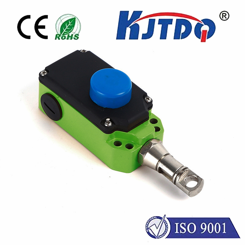
- Mechanical Lever Switches: The most common and affordable choice (e.g., KW12-3). A physical lever arm is pressed by the moving part, closing or opening an electrical circuit.
- Pros: Cheap, simple wiring, generally robust.
- Cons: Prone to physical wear, potential for false triggers from vibration if not damped/mounted securely, lever can bend or snag, repeatability (how precisely they trigger at the exact same point every time) can be lower than other types.
- Mounting Tip: Use adjustable mounts or printed brackets for fine-tuning trigger position.
- Optical Endstops: Utilize a beam of light (usually infrared) between an emitter and a sensor (or a reflective sensor). Triggering occurs when the flag attached to the CNC axis interrupts this beam.
- Pros: Excellent repeatability, no physical contact means no wear on the switch itself, immune to mechanical vibration, very fast response.
- Cons: Typically more expensive than mechanical switches, requires alignment for the flag to break the beam cleanly, ambient light can (though rarely) cause issues if poorly shielded.
- Mounting Tip: Often come with dedicated mounts or easily integrated into printed carriers. Alignment jigs are helpful.
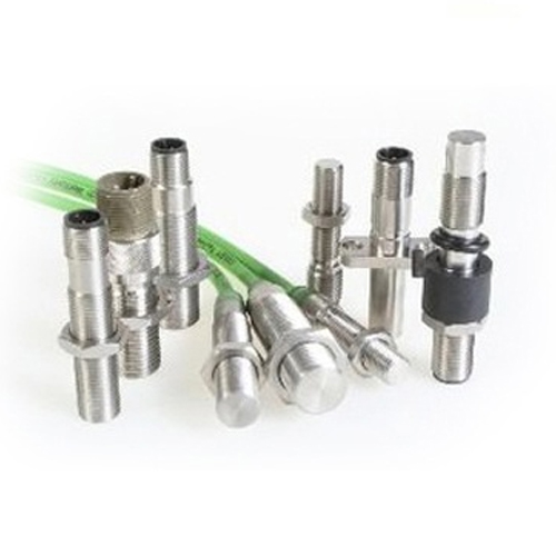
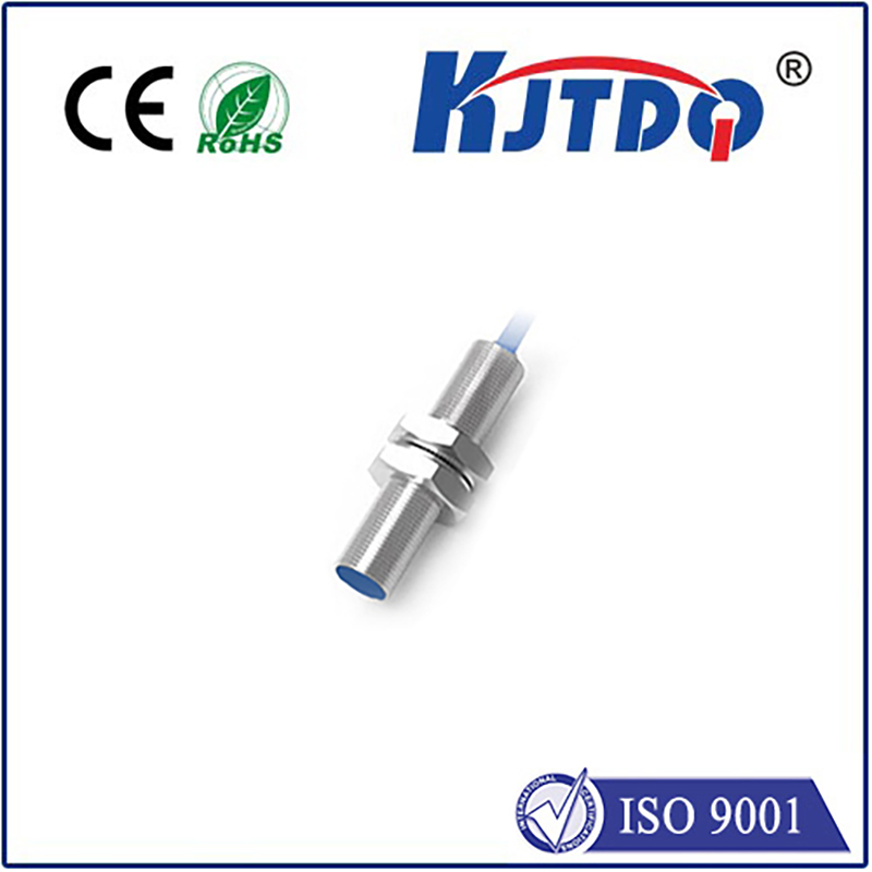
- Magnetic Proximity Sensors: Detect the presence of a nearby magnet without physical contact.
- Pros: Very durable (sealed units available), high repeatability, contactless operation.
- Cons: Relatively expensive compared to mechanical, requires mounting both the sensor and a magnet precisely on the moving axis, triggering distance is critical and must be consistent.
Implementing Your MPCNC Limit Switches: Key Steps
- Strategic Positioning:
- Homing Switches Only: Typically placed near one end of each axis (often the positive X/Y and either top or bottom Z). Machine homes to these switches.
- Travel Limit Switches: Less common on DIY MPCNC builds but possible. Require switches at both ends of each axis travel to prevent movement beyond those points in either direction. Homing usually still uses one end. Homing setups are overwhelmingly standard.
- Mounting: Use printed brackets, adjustable mounts, or the solutions provided with your chosen switches. Ensure the switch trigger point is consistent and reliable. Avoid positions where chips or dust could accumulate and interfere with mechanical levers or optical paths. Secure wiring to prevent snagging.
- Wiring Wisely: How you wire depends on the switch type (Normally Open - NO, or Normally Closed - NC) and your controller/firmware configuration.
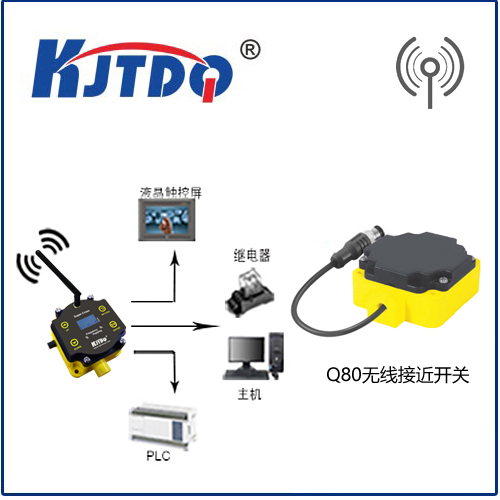
- Gcode and Firmware: Most CNC controller boards (like RAMPS, SKR, GRBL boards) have dedicated endstop input pins (usually labeled
X_MIN, Y_MAX, etc.). Crucially consult your controller’s pinout diagram.
- NO vs. NC Wiring: NC wiring is often preferred for safety. In an NC circuit, the switch normally allows current flow. Triggering the switch breaks the circuit. The advantage? If a wire breaks or becomes disconnected, the controller sees an “open” circuit (triggered state) and stops the machine. With NO wiring, a broken wire looks like the switch was never triggered (safe state), potentially allowing a crash. Marlin/GRBL readily configures for either.
- Pull-up/Pull-down: The controller input pins typically require pull-up resistors. These are often built into the controller board or firmware-enabled. Check documentation.
- Firmware Configuration (Marlin/GRBL): This is critical! Open your firmware configuration file (
Configuration.h for Marlin).
- Enable Homing: Set
#define USE_XMAX_PLUG (or similar for your controller pins - X_MIN, Y_MAX etc.) to true for each axis you have equipped. Define #define Z_HOMING_HEIGHT appropriately if homing Z down (common).
- Set Homing Direction: Configure
#define HOME_DIR (e.g., -1 for moving negative direction to find home).
- Pull-ups: Usually enabled globally (
#define ENDSTOPPULLUPS).
- Switch Logic: Define
#define X_MIN_ENDSTOP_INVERTING (or X_MAX, etc.) to true or false depending on if your switch is NO or NC and the board’s logic. Getting this wrong means the switch won’t trigger when expected or might trigger constantly. Test meticulously!
- Compile & Upload: Save your config, compile the firmware, and upload it to your controller.
- Testing & Calibration:
- Safely First! Manually jog the machine slowly towards each switch. Ensure movement stops immediately upon trigger.
- Check Homing Routine: Command
G28 (home all axes) or G28 X (home X only). Observe the machine slowly move until it triggers each