inducer motor limit switch
- time:2025-08-04 13:13:33
- Click:0
Induction Motor Limit Switches: Essential Guards for Precision and Protection
The rhythmic hum of an induction motor is the heartbeat of countless industrial processes. From precisely positioning robotic arms to lifting heavy loads on cranes, these workhorses rely on more than just power to operate safely and effectively. Enter the induction motor limit switch – a seemingly simple component that plays a critical role in defining boundaries and preventing disaster. Understanding how these switches safeguard induction motors and the systems they drive is fundamental to reliability, safety, and operational integrity.
Imagine a powerful overhead crane hoisting a multi-ton load. Without precise control, it could easily overshoot its target position, slam into structural supports, or worse, drop its load catastrophically. Similarly, consider a conveyor belt carrying delicate packages; if it travels too far, products spill, motors strain, and damage occurs. This is where the limit switch earns its keep. Acting as the “eyes” at the end of travel, it provides crucial feedback to the motor control system, signaling when a physical boundary has been reached. Upon activation, the switch interrupts the motor’s control circuit or signals the drive controller to immediately halt or reverse the motor’s operation, preventing over-travel, collisions, and potential damage to machinery, products, or personnel.
How Induction Motor Limit Switches Function: The Safety Link
While the induction motor itself provides the motive force, the limit switch acts as a protective sentinel. Here’s the core interaction:
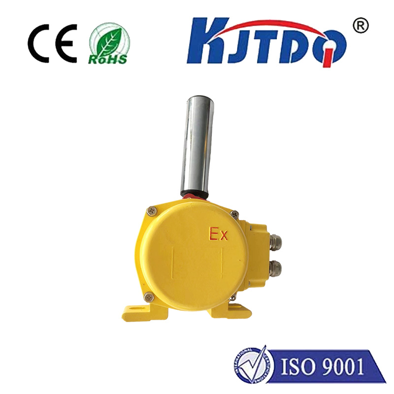
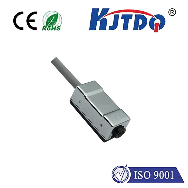
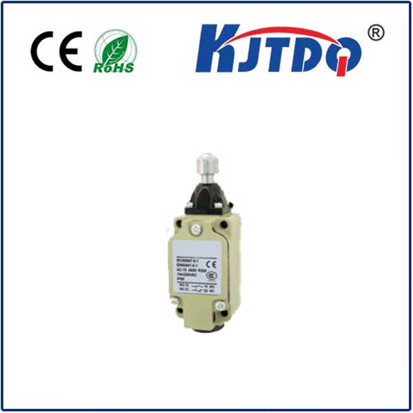
- Mechanical or Proximity Trigger: A moving part of the machine (like the crane trolley or a sliding gate) physically contacts a lever, roller, or plunger on a mechanical limit switch. Alternatively, non-contact proximity switches (inductive, capacitive, or photoelectric) detect the presence of the object without physical touch.
- Electrical Signal Change: This physical interaction (or proximity detection) causes an internal mechanism within the limit switch to change its electrical state. Typically, this means opening (breaking) or closing (making) electrical contacts within the switch. These contacts are hardwired into the motor control circuit.
- Motor Control Response: The change in the limit switch’s contact state is detected by the motor starter, contactor, or Variable Frequency Drive (VFD) controlling the induction motor. If the switch opens the circuit upon reaching a limit, it directly cuts power to the contactor coil holding the main power contacts closed, causing the motor to stop abruptly (often using auxiliary contacts). If signaled to a PLC or VFD, it initiates a controlled stop or reversal sequence.
- Travel Limitation Achieved: The motor stops or reverses direction, preventing the driven mechanism from moving beyond its designated safe operating zone. This prevents mechanical overload, potential jamming, structural damage, and unsafe conditions.
Choosing and Implementing the Right Limit Switch

Not all limit switches are created equal, especially when paired with the demands of controlling an induction motor. Selection hinges on several factors:
- Environment: Is it dusty, wet, corrosive, or exposed to extreme temperatures? IP (Ingress Protection) ratings are crucial. Harsh environments demand heavy-duty or hermetically sealed switches.
- Actuation Force & Type: What force can the moving part exert? Does it require a sturdy roller lever for linear motion, a wobble stick for multi-directional approach, or a non-contact solution?
- Electrical Ratings: The switch contacts must reliably handle the voltage and, critically, the current (especially inrush current) of the motor control circuit it interrupts. Undersized contacts can weld shut or fail prematurely.
- Repeatability & Precision: How critical is the exact stopping point? High-precision applications may need switches with minimal actuation differential (the distance between activation and reset).
- Contact Configuration (NO/NC): Normally Open (NO) contacts close upon actuation; Normally Closed (NC) contacts open upon actuation. NC contacts are often preferred for safety circuits (failsafe principle) because a broken wire will simulate an activation signal, stopping the motor. NO contacts are common for straightforward ‘stop at end’ signals.
Beyond the Basics: Ensuring Reliability in Motion Control
The integration of limit switches into induction motor systems demands careful engineering:
- Mounting and Positioning: Switches must be securely mounted to withstand vibration and impact. Their position must be precisely calibrated to trigger before the physical limit is actually reached, allowing for motor deceleration time. Backup or redundant limit switches are often employed for critical safety functions.
- Protection from Over-travel: Switches should ideally be positioned so that if they fail, the machine encounters a mechanical hard stop before catastrophic failure occurs. Relying solely on the switch without a physical backup is risky.
- Debounce and Timing: Mechanical switches can “bounce” upon actuation, causing multiple rapid on/off signals. Control systems often incorporate debounce logic (in hardware or software) to ensure a single, clean signal is registered. Timing coordination is also vital when multiple switches or sequences are involved.
- Integration with VFDs/PLCs: Modern systems often use the limit switch signal as an input to a PLC or VFD. This allows for more sophisticated control, such as controlled ramp-down stops, automatic reversal sequences, or integration into overall machine safeguarding systems.
Why Induction Motor Limit Switches Are Non-Negotiable
Neglecting or improperly maintaining limit switches can have severe consequences:
- Catastrophic Equipment Damage: Motors driven beyond their mechanical limits can cause bearing failures, shaft breakage, gearbox destruction, or damage to driven machinery.
- Production Downtime: Recovering from a collision or repairing damaged equipment leads to significant costly delays.
- Safety Hazards: The most critical failure mode. Over-traveling mechanisms can crush objects, trap personnel, or cause load drops, posing grave risks. Limit switches are fundamental safety devices.
- Reduced Product Quality: In processes requiring precise positioning (e.g., cutting, filling), failure to stop accurately leads to scrap and rework.
Proactive Maintenance is Key
Ensuring limit switch reliability for induction motor protection requires vigilance:
- Regular Inspection: Check for physical damage, loose mounting, corrosion, and buildup of contaminants (oil, dust, chips).
- Functional Testing: Periodically verify correct operation by manually actuating the switch and confirming the motor responds appropriately in a safe manner.
- Contact Cleaning/Replacement: Contacts can pit, burn, or become coated over time. Clean with appropriate solvents or replace the switch if contacts show wear.
- Adjustment Checks: Vibration or wear can cause actuation points to drift. Periodically verify the switch triggers at the correct position.
Conclusion
While often overshadowed by the motor itself, the induction motor limit switch is an indispensable guardian. It provides the vital physical boundary detection necessary to harness the power of induction motors safely and precisely. By understanding their function, selecting the right type for the demanding conditions, integrating them thoughtfully into the control system, and maintaining them diligently, engineers and technicians ensure the longevity of equipment, the safety of personnel, and the smooth, uninterrupted flow of industrial operations. It’s a small component with an absolutely critical mission: defining the limits of motion to protect everything within them.


