brake limit switch - KJT
搜索

brake limit switch

  • time:2025-08-04 12:47:52
  • Click:0

The Brake Limit Switch: Your Machinery’s Unsung Safety Sentinel

Imagine a massive industrial crane lifting tons of material high above a busy factory floor. Or picture a highspeed automated production line where robotic arms move with lightning speed. Now imagine the brakes on these systems failing to engage at precisely the right moment. The potential consequences – from catastrophic equipment damage to severe human injury – are unthinkable. This is where a seemingly small but critically important component steps in: the brake limit switch.

Far more than just another sensor, the brake limit switch is a dedicated safety watchman. Its singular, vital mission: to confirm unequivocally whether a brake is fully applied or fully released. This binary verification is non-negotiable for safe machine operation.

But What Exactly Is a Brake Limit Switch?

At its core, a brake limit switch is a robust position-sensing device. It’s physically mounted in close proximity to the braking mechanism it monitors – be it on an electric motor brake, a caliper, or a larger industrial brake assembly. Unlike complex control systems, its function is beautifully simple: it detects the physical position of a specific part of the brake actuator or linkage.

  • Brake Applied Position: When the brake successfully engages, it physically moves a target (like a lever, cam, or plunger) that actuates the switch. This sends a clear electrical signal: “Brake is ON. Holding.
  • Brake Released Position: Conversely, when the brake is fully disengaged, the target moves away, typically causing the switch to return to its normal state. This signal translates to: “Brake is OFF. Clear for motion.

This direct physical linkage ensures a high degree of reliability in its feedback – it’s sensing the actual mechanical state of the brake itself.

Why Is This Verification So Crucial?

The signals generated by the brake limit switch are fed directly into the machine’s safety control circuit or its Programmable Logic Controller (PLC). This feedback isn’t just informative; it’s absolutely essential for enabling or preventing dangerous machine actions. Consider these critical scenarios:

  1. Preventing Accidental Movement (Hoisting/Lifting): In overhead cranes, elevators, or any vertical lifting application, the brake must be securely applied before the load can be safely suspended. The brake limit switch provides the ‘Brake Applied’ confirmation that allows the hoist motor controller to de-energize only after it knows the brake is holding the load. Without this signal, the motor could release while the brake isn’t engaged, leading to a dangerous runaway load.
  2. Enabling Safe Motion (Machinery): On rotating equipment like large motors, fans, or conveyors, the brake must be fully released before the motor is allowed to start spinning. The ‘Brake Released’ signal from the limit switch acts as a permissive. The motor control circuit will only initiate start-up once it receives this all-clear confirmation. Attempting to start a motor against a partially engaged brake could cause serious damage to the motor, the brake, or the drivetrain.
  3. Emergency Stop Verification: During an emergency stop (E-stop) event, immediate brake application is vital. The brake limit switch provides positive feedback that the brake has indeed engaged as commanded. This confirmation is vital for safety system integrity logging and can trigger further safety actions if the brake fails to apply.
  4. Over-Travel Protection: In some configurations, particularly on larger linear brakes or clamps, limit switches can also act as the final safeguard to prevent mechanical over-travel beyond safe limits if primary positioning systems fail.

Beyond Safety: Enhancing Control and Preventing Damage

While safety is paramount, brake limit switches contribute significantly to operational efficiency and equipment longevity:

  • Eliminating Drag and Wear: Ensuring the brake is fully released before motion starts prevents unnecessary rubbing and friction. This reduces energy consumption and significantly extends the lifespan of both the brake linings/pads and the motor by preventing premature wear.
  • Optimizing Cycle Times: Reliable brake confirmation allows control systems to sequence operations more precisely, minimizing unnecessary delays waiting for ambiguous brake states. This can lead to smoother operation and potentially faster cycle times in automated processes.
  • Diagnostic Insight: Consistent failure of a brake to reach its commanded position (indicated by the absence of the expected limit switch signal) is a clear diagnostic flag. It prompts timely maintenance checks for issues like air in hydraulic brake lines, solenoid failure on electromagnetic brakes, or excessive mechanical wear.

Robust Construction for Demanding Environments

Given their critical role in often harsh industrial settings, brake limit switches are designed for durability and reliability:

  • Rugged Enclosures: Typically housed in robust metal or high-impact plastic bodies rated IP67 or higher, protecting against dust, moisture, oils, and physical impacts.
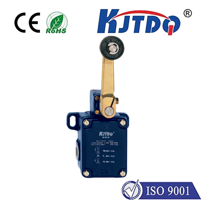
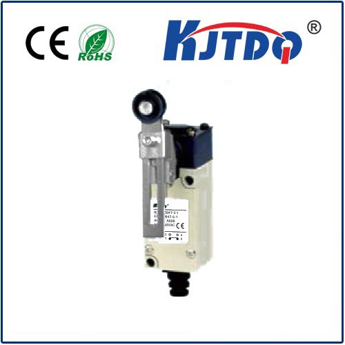
  • Diverse Actuation Types: Options include roller levers, plungers, and whisker types to suit different mounting configurations and actuation mechanisms.
  • Reliable Contacts: Built with high-quality electrical contacts (often gold-plated) to handle switching loads reliably over thousands, even millions, of cycles.
  • Varied Electrical Ratings: Available with different voltage/current ratings (e.g., 24VDC, 120VAC, 240VAC) and contact configurations (SPDT, DPDT) to integrate seamlessly into diverse control systems.

Integration and Maintenance: Keeping the Sentinel Sharp

For a brake limit switch to perform its vital function effectively, correct installation and alignment are paramount. The switch must be precisely positioned so that the actuator target reliably trips it in the fully applied and/or fully released positions. Any misalignment can lead to false signals or complete failure to actuate.

Regular inspection and maintenance should include:

  • Checking for secure mounting and freedom from vibration-induced loosening.
  • Ensuring the actuator lever or plunger moves freely without binding or obstruction.
  • Inspecting for physical damage to the switch body, actuator, or wiring.
  • Periodically testing the signal output using a multimeter or observing the PLC input status during brake cycling.

The Indispensable Guardian

In the complex symphony of industrial machinery, the brake limit switch plays a solo part that, while often unnoticed, is irreplaceable. It is the definitive voice confirming that a machine is anchored safely or cleared for controlled motion. By providing this binary truth about brake position, it forms a critical link in the safety chain, actively preventing accidents and protecting both personnel and valuable equipment. Its role in preventing damage and optimizing performance further underscores its value beyond pure safety. When it works perfectly, it remains unseen. But when its signal is absent or incorrect, its vital importance becomes immediately, often critically, apparent. Never underestimate the power of this small switch to guarantee safe stops and enable secure starts.
Recommended products