hoist limit switch
- time:2025-07-30 16:22:40
- Click:0
Hoist Limit Switches: The Silent Guardians Preventing Crane Catastrophes
Imagine a multi-ton load suspended high above a factory floor, smoothly ascending towards its destination. Suddenly, the hoist motor shows no sign of stopping, propelling the load relentlessly towards the crane’s superstructure. Without a critical, often overlooked component, this scenario could end in devastating impact, snapped cables, and potential disaster. That unsung hero? The hoist limit switch.
Far more than a simple on/off device, the hoist limit switch is a fundamental safety system engineered to prevent over-travel. Its sole purpose is to act as the ultimate failsafe, automatically cutting power to the hoist motor the moment the hook block or load reaches its predetermined upper or lower travel limit. This non-negotiable safety function protects personnel, the load, the crane structure itself, and surrounding equipment from the catastrophic consequences of a runaway hoist.
How Does This Vital Safety Mechanism Work?
At its core, a hoist limit switch is a precision-triggered control device. It does not typically control normal hoisting operations; that’s the operator’s domain. Instead, it sits patiently monitoring travel, ready to intervene only when absolute limits are approached. The mechanism involves:

- The Trigger Point: This is physically set on the crane’s structure – often near the top of the girder for the upper limit and at the boom tip or designated safe lower point. This point must be precisely calibrated.
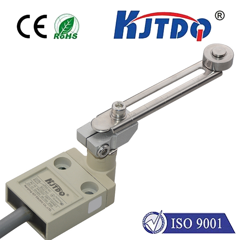
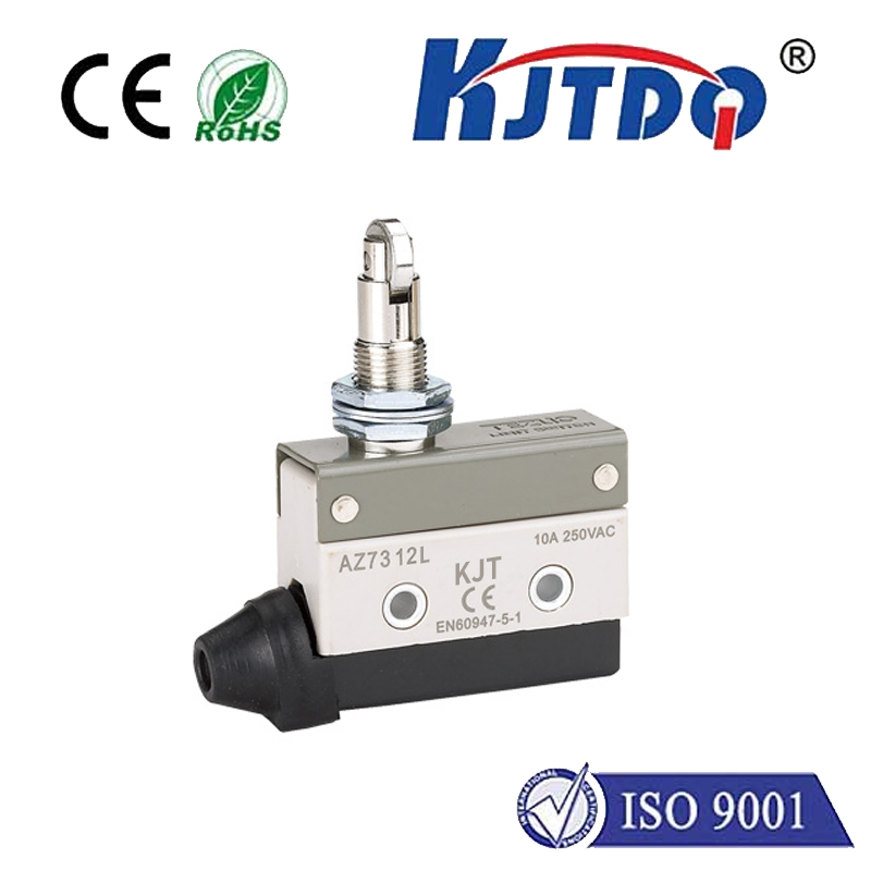
- The Actuator: Mounted on the moving hook block (or sometimes the rope drum), this component physically engages the switch. Common types include:
- Lever Arms: A protruding arm that gets pushed or pulled.
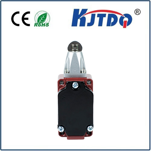
- Roller Plungers: A spring-loaded roller depressed by contact.
- Rotary Cams: Attached to the drum, rotating to trigger at specific points.
- Magnetic Proximity: Non-contact, sensing a ferrous target passing by.
- The Switch Mechanism: When the actuator engages, it forces the switch contacts inside to change state (typically opening the circuit). This critical action sends a signal to the crane’s control system.
- Result: The control system interprets the signal and immediately cuts power to the hoist motor in the direction of over-travel (raising for upper limit, lowering for lower limit). Crucially, the hoist should only be allowed to operate in the opposite direction to move away from the limit.
Why Hoist Limit Switches are Non-Negotiable for Safety
Compliance with rigorous standards like OSHA 1910.179 and ASME B30.2 mandates properly functioning hoist limit switches on virtually all overhead lifting equipment. Their critical safety functions include:
- Preventing Two-Blocking: The upper limit switch is primarily designed to stop the hook block from colliding with the trolley or crane bridge – a catastrophic event known as two-blocking, which can instantly snap cables and drop loads.
- Preventing Drum Overwinding: On the lower end, the switch prevents the hook block from crashing into the floor or, critically, stops the rope drum from overwinding (where the rope spools over itself under tension), which can cause severe rope damage and failure.
- Protecting Crane Structure: Over-travel collisions generate immense shock loads capable of bending girders, damaging end trucks, and compromising the entire crane’s structural integrity.
- Safeguarding Personnel: By preventing uncontrolled drops or falling debris from collisions, limit switches directly protect workers below and crane operators.
- Asset Protection: Avoiding impacts and overloads significantly extends the lifespan of the hoist motor, gearbox, wire rope, and crane structure.
Choosing the Right Hoist Limit Switch: Key Factors
Not all limit switches are created equal. Selecting the appropriate type and configuration is vital for reliable protection:
- Type of Motion: Rotary cam switches are often preferred for drum rotation limits, while lever/roller types suit hook block travel limits.
- Environment: Harsh conditions (dust, moisture, chemicals, extreme temperatures) demand robust switches with high IP ratings (e.g., IP65, IP67). Explosion-proof versions are essential in hazardous locations.
- Duty Cycle: Frequent operation requires switches designed for high mechanical endurance.
- Precision Needs: Applications requiring very exact stopping points may need adjustable precision switches or non-contact sensors.
- Redundancy: Critical lifts often employ redundant systems – two independent limit switches – ensuring safety even if one fails. Self-monitoring switches that detect internal failures are also highly valuable.
- Fail-Safe Design: The switch must default to a safe state (power cut) upon failure or loss of control signal. Gravity lowering after an upper limit trigger must be prevented unless a controlled override is specifically designed and engaged.
Installation, Calibration, and Maintenance: The Bedrock of Reliability
A hoist limit switch is only as effective as its installation and upkeep. Regular maintenance and testing are mandated by safety standards and common sense:
- Professional Installation: Switches must be mounted securely and actuators positioned precisely relative to the trigger points. Wiring must be protected and comply with electrical codes.
- Accurate Calibration: Critical Step! The switch must trigger before the hook block or load reaches the physical obstruction or drum overwind point. There must be a defined safety buffer. Calibration should be done by qualified personnel following OEM procedures and verified with the load block unloaded initially, then confirmed under safe conditions with a test weight if possible.
- Scheduled Inspections and Testing: This is not optional. Checks should include:
- Physical condition of switch, actuator, and mounting hardware.
- Freedom of movement for levers/rollers (no binding or obstruction).
- Security of wiring connections.
- Operational Testing: Functionality must be tested at least semi-annually (often more frequently per regulation or risk assessment) by slowly running the hook block into the limit switch under no load and verifying:
- Power cuts instantly in the over-travel direction.
- Power remains available to move away from the limit.
- No unintended resetting occurs during return travel.
- (For redundant systems) Testing each switch independently.
- Preventive Replacement: Worn switches or actuators should be replaced proactively based on inspection findings or manufacturer service life recommendations, rather than waiting for failure.
Beyond the Basic Limit: Modern Enhancements
While traditional electromechanical switches remain prevalent, technology offers enhancements:
- Absolute Encoders: Mounted on the drum shaft, these provide precise position feedback, allowing programmable soft limits in the control system before the hard limit switch is reached, offering an extra layer of protection and potentially smoother operation. However, they do not replace the requirement for a physical limit switch hard stop.
- Smart Switches: Some modern switches offer diagnostic outputs, providing real-time status on health and actuation, feeding into predictive maintenance systems.
The hoist limit switch operates silently in the background, unseen during normal operations. Yet, its role is paramount. It stands as the final, fail-safe barrier against some of the most dangerous failures possible in lifting operations. Understanding its function, ensuring its correct selection, meticulous calibration, and rigorous maintenance isn’t just about compliance; it’s the foundation of a truly safe lifting culture. Never underestimate the power of this small device to prevent a major catastrophe. Its reliability is the difference between a routine lift and a potentially devastating incident.