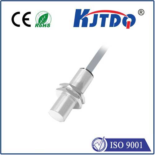
metal proximity sensor arduino - KJT
搜索

metal proximity sensor arduino

  • time:2025-07-20 08:18:04
  • Click:0

Unlocking Detection Magic: Your Guide to Metal Proximity Sensors with Arduino

Metal proximity sensor arduino projects unlock a world where machines intuitively sense their metallic surroundings. Whether you’re building an automated factory line, a smart security system, or an interactive art installation, understanding how to integrate inductive proximity sensors with an Arduino is a fundamental and powerful skill. These remarkable devices detect metal objects without physical contact, offering reliability and durability perfect for countless applications. This guide demystifies the process, walking you through core concepts, essential wiring, practical coding, and real-world ideas.

The “Sixth Sense”: How Inductive Proximity Sensors Work

At the heart of most metal proximity sensors lies the principle of electromagnetic induction. Here’s the core magic:

  1. Internal Oscillator: The sensor contains a coil through which an oscillating high-frequency current flows. This generates a dynamic electromagnetic field radiating from the sensor’s active face.
  2. Metallic Target Influence: When a conductive metal object enters this field, eddy currents are induced within the metal itself. These currents are microscopic loops generated by the changing magnetic field.
  3. Energy Drain & Signal Shift: The creation of these eddy currents essentially draws energy away from the sensor’s internal oscillator circuit. This energy loss causes a measurable change – typically a reduction in the oscillation amplitude.
  4. Detection & Output: Sophisticated circuitry within the sensor monitors this amplitude change. When the change exceeds a preset threshold (indicating a target is within the specified sensing range), the sensor switches its output state.

Key Sensor Characteristics Arduino Users Need to Know

  • Normally Open (NO) vs. Normally Closed (NC): This defines the sensor’s resting state when no target is detected.
  • NO Sensor: Output is OFF (LOW for NPN, OPEN for PNP) until a target is detected, then it turns ON (HIGH for NPN, CLOSED for PNP).
  • NC Sensor: Output is ON (HIGH for NPN, CLOSED for PNP) until a target is detected, then it turns OFF (LOW for NPN, OPEN for PNP).
  • Choosing the right type depends entirely on your desired logic in the Arduino sketch.
  • NPN vs. PNP Outputs: This refers to the type of transistor used in the sensor’s output stage, determining how it interfaces electrically.
  • NPN (Sinking): The most common type for microcontroller use. When active, the output pin connects the signal wire internally to the sensor’s Negative (0V/GND) supply wire. Requires a pull-up resistor on the Arduino input pin.
  • PNP (Sourcing): When active, the output pin connects the signal wire internally to the sensor’s Positive (V+) supply wire. Requires a pull-down resistor on the Arduino input pin.
  • For Arduino compatibility, NPN sensors are generally simpler to interface.
  • Sensing Range: The maximum distance at which the sensor can reliably detect a standard target (usually mild steel). Accurate positioning within this range is critical.
  • Hysteresis: A small built-in difference between the “turn-on” and “turn-off” distances. This prevents rapid switching (chatter) if a target lingers right at the edge of the sensing range.

Connecting the Dots: Wiring Your Metal Sensor to Arduino

Let’s translate theory into practice with a typical wiring example using a common 3-wire DC NPN NO inductive proximity sensor:

  1. Sensor Power (Brown Wire): Connect to the Arduino’s 5V output pin. (Check sensor datasheet! Some industrial sensors require 10-30V DC; use an external PSU and level shifting if needed).
  2. Sensor Ground (Blue Wire): Connect to the Arduino’s GND pin.
  3. Sensor Signal (Black Wire - NPN NO): This is the output wire.
  • Connect directly to your chosen Arduino digital input pin (e.g., D2).
  • Crucially, add a Pull-Up Resistor: Connect a resistor (typically 4.7kΩ or 10kΩ) between the signal wire (at D2) and the Arduino’s 5V pin. This ensures D2 reads HIGH when the sensor is inactive (NPN open circuit), and LOW when the sensor detects metal (NPN sinks the signal to GND).

Arduino Sketch Essentials: Reading the Detection Signal

The code logic is refreshingly straightforward. The core task is to read the state of the digital input pin connected to the sensor’s signal wire.

const int sensorPin = 2; // Define pin connected to sensor's signal wire
void setup() {
Serial.begin(9600); // Start serial communication for debugging
pinMode(sensorPin, INPUT); // Set sensor pin as INPUT
}
void loop() {
int sensorState = digitalRead(sensorPin); // Read the pin state
// For an NPN NO sensor with PULL-UP resistor:
// - HIGH means NO metal detected (NPN output is OFF/open circuit)
// - LOW means metal IS detected (NPN output is ON/sinking to GND)
if (sensorState == LOW) {
Serial.println("Metal Detected!"); // Action when metal is present
// Add your actions here: turn on LED, trigger relay, etc.
} else {
Serial.println("No Metal..."); // Action when no metal
// Add actions for absence of metal if needed
}
delay(100); // Small delay for readability, adjust as needed
}

Key Code Notes:

  • Logic Depends on Wiring: This logic (LOW == detection) works specifically for an NPN NO sensor used with a pull-up resistor. If using an NC sensor or a PNP sensor, the logic will be inverted.
  • Debouncing (Optional but Recommended): While the sensor’s hysteresis helps, incorporating a simple software debounce can make detection even more reliable, especially if the signal seems erratic. Filter out very short LOW pulses by implementing a time-delay check in your if condition.
  • Going Beyond Serial: Replace the Serial.println() commands with code to control LEDs, relays, buzzers, servos, or other Arduino outputs to react meaningfully to detection events.

Bringing Ideas to Life: Metal Detection Arduino Project Ideas

The combination of metal proximity sensors and Arduino opens up vast possibilities:

  1. Production & Automation: Count metallic parts on a conveyor belt, detect the position of a machine arm/tool, verify the presence of a metal component before initiating a process step.
  2. Security & Safety: Create non-contact door/window position sensors (detect hinge/metal frame movement), build hidden metal detectors for restricted areas, implement safety interlocks on machinery requiring guards.
  3. Vehicles & Robotics: Develop basic object avoidance for robots navigating metal environments, detect wheel rotation (using bolts on the hub) for speed sensing, determine chassis position for parking aids.
  4. Interactive Experiences: Build musical instruments triggered by waving metal objects, create interactive exhibits that respond to user-held metal tokens, design kinetic sculptures that react to nearby metal structures.
  5. Home & Workshop: Monitor mailbox flags (if metal), detect garage door position for automation, build a tool presence detector in a drawer, create a simple coin sorting machine prototype.

Mastering Your Metal Proximity Sensor Arduino Setup

Success hinges on understanding your specific sensor’s characteristics. Always consult the sensor’s datasheet – it is your definitive guide for wiring (pinout, voltage), output type (NPN/PNP, NO/NC), and sensing specifications (range, hysteresis, target material suitability). Pay close attention to whether it requires an external power supply beyond the Arduino’s 5V.

When wiring, double-check connections before powering on. Use the
Recommended products