rpm proximity sensor
- time:2025-07-16 08:45:52
- Click:0
Unlocking Precision: Your Essential Guide to RPM Proximity Sensors
Accurate rotational speed measurement is the silent heartbeat of countless machines. From the whirring motors in manufacturing plants to the powerful engines propelling vehicles, knowing exactly how fast something spins is critical for efficiency, safety, and control. Enter the RPM proximity sensor – a sophisticated, non-contact solution that reliably captures this vital data. But how does it achieve this feat, and why is it often the preferred choice? Let’s delve into the world of these remarkable sensors.
At its core, an RPM proximity sensor is a type of non-contact sensor designed specifically to detect the presence or absence of a metallic target and, crucially, count the frequency of those detection events to calculate revolutions per minute (RPM). Unlike mechanical tachometers that require physical contact, proximity sensors operate remotely, eliminating wear, slippage, and potential damage to rotating components. This makes them exceptionally robust and suitable for demanding industrial environments.
How Does an RPM Proximity Sensor Actually Work?
The magic lies in electromagnetic principles. The most common types used for RPM measurement are inductive proximity sensors and Hall effect sensors.
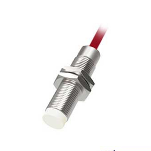
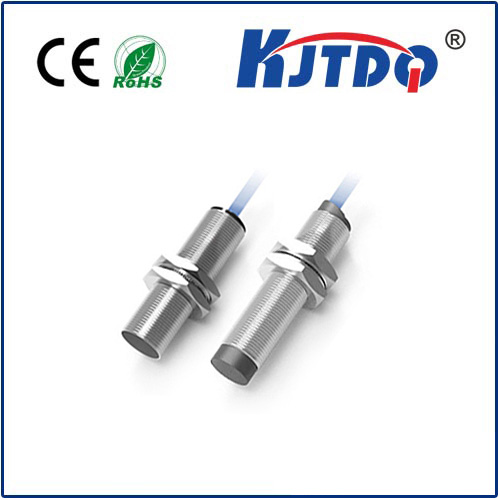
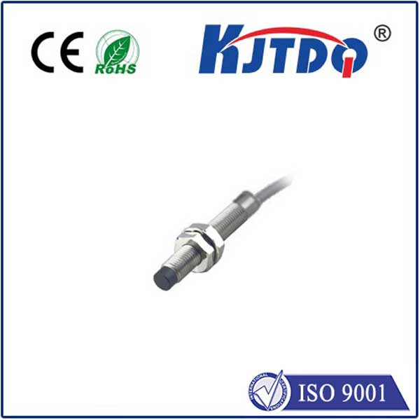
- Inductive Proximity Sensors: These generate an oscillating electromagnetic field from a coil. When a metallic target (like a gear tooth, keyway, or dedicated flag) moves into this field, it induces tiny electrical currents called eddy currents within the metal. This disturbance absorbs energy from the sensor’s coil, causing a detectable change in the oscillation amplitude or frequency. This change triggers the sensor’s internal electronics to produce a clean, digital output signal (usually a square wave pulse) each time the target passes by.
- Hall Effect Sensors: These utilize semiconductors and the Hall effect principle. When a magnetic target (like a magnet embedded in a shaft or a ferrous gear tooth passing a small magnet integrated near the sensor) approaches, it disturbs the magnetic flux through the semiconductor. This disturbance generates a small voltage (Hall voltage) across the semiconductor. This voltage change is amplified and conditioned to produce a similar digital output pulse per target pass.
The Key to RPM Measurement: Regardless of the specific technology (inductive or Hall effect), the core function for RPM is the same. The sensor generates one distinct electrical pulse for each target it detects passing its face. By counting the number of these pulses occurring within a specific time window (say, one minute or fractions thereof, managed by an external controller, PLC, or dedicated tachometer), the rotational speed in revolutions per minute (RPM) is precisely calculated. If the target has multiple teeth or markers per revolution (e.g., a 60-tooth gear), the sensor counts the pulses per unit time and the RPM calculation simply divides this count by the number of targets per revolution.
Why Choose an RPM Proximity Sensor? Key Advantages
The widespread adoption of these sensors isn’t accidental. They offer significant benefits over contact-based methods:
- Non-Contact Operation: Eliminates wear, friction, and potential damage to shafts or bearings, leading to dramatically reduced maintenance needs and longer operational lifespans.
- High Reliability & Accuracy: Free from mechanical wear and slip, they provide consistent, precise RPM readings even at very high speeds (often exceeding 10,000 RPM for certain models) or very low speeds. This accuracy is vital for process control and quality assurance.
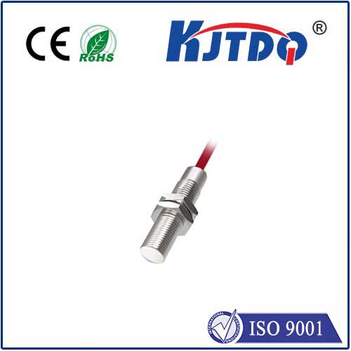
- Robust Construction: Designed to withstand harsh industrial environments – resistant to oil, grease, dust, vibration, and common chemicals. Many feature rugged stainless steel housings.
- Fast Response Times: Capable of detecting rapid changes in speed, making them ideal for dynamic applications and safety cut-offs.
- Versatility: Can be used with a wide variety of target materials (ferrous metals for inductive, magnetic for Hall effect) and configurations (gears, keyphasors, sprockets, dedicated flags, even screw heads).
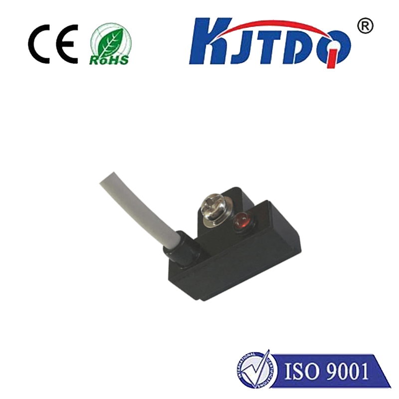
- Compact Size & Easy Integration: Their typically small form factor allows for installation in space-constrained locations.
Core Applications: Where RPM Proximity Sensors Shine
RPM proximity sensors are indispensable across numerous sectors:
- Industrial Automation & Motor Control: Monitoring conveyor speeds, spindle speeds on CNC machines, pump/motor RPMs, and synchronizing processes. Preventing equipment overspeed is a critical safety function.
- Automotive & Transportation: Measuring engine RPM (crankshaft/camshaft position/speed), wheel speed for ABS systems, transmission shaft speeds, and turbocharger monitoring.
- Aerospace: Monitoring turbine engine speeds (NG, N1), gearbox speeds, and auxiliary power units (APUs).
- Power Generation: Overspeed detection and control on turbines (gas, steam, hydro) and generators.
- Material Handling: Controlling the speed of rollers, winders, and feeders.
- Packaging Machinery: Ensuring precise synchronization of moving parts based on rotational speed.
Selecting the Right RPM Proximity Sensor: Key Considerations
Choosing the ideal proximity sensor for RPM measurement involves evaluating several factors:
- Technology: Inductive (best for ferrous metals) vs. Hall Effect (requires magnetic targets or ferrous targets passing a magnet, and often handles smaller air gaps).
- Target Material & Geometry: Size, shape (tooth width), and material (steel, aluminum etc.) of the target significantly influence sensor choice and required sensing distance.
- Sensing Distance: The maximum air gap between the sensor face and the target that allows reliable detection. Ensure adequate clearance under all operating conditions.
- Operating Speed Range: Minimum and maximum RPM the sensor can accurately detect. Consider both normal operating range and potential extremes.
- Output Signal Type: NPN/PNP transistor, or Namur (intrinsically safe). Must be compatible with your control system (PLC, counter, drive) input.
- Electrical Requirements: Supply voltage (commonly 10-30V DC) and current consumption.
- Environmental Conditions: Temperature range, exposure to chemicals, moisture (IP rating), vibration levels.
- Mounting: Physical constraints and required orientation relative to the target.
By understanding these principles, advantages, applications, and selection criteria, you can effectively leverage the power of Rpm Proximity Sensors to achieve precise speed control, enhanced equipment protection, and optimized performance across countless mechanical systems. Their ability to deliver reliable, non-contact rpm data makes them a fundamental tool in modern engineering.