proximity sensor components
- time:2025-07-15 08:29:27
- Click:0
The Essential Anatomy of Proximity Sensors: Unpacking Core Components
They sense without touching, enabling seamless interactions in countless devices – from your smartphone screen waking as you approach, to factory robots avoiding collisions, and car doors unlocking with a touch. Proximity sensors are the hidden guardians of modern technology, making the impossible feel effortless. But how do these remarkable devices actually work? The magic lies entirely within their meticulously designed proximity sensor components. Understanding these internal building blocks isn’t just technical curiosity; it’s key to appreciating their diverse capabilities and selecting the right sensor for any application.
Beyond the Black Box: Defining the Core Function
At its heart, a proximity sensor detects the presence or absence of an object within a specific range without physical contact. It achieves this by emitting a field or beam and monitoring changes caused by a target object. This fundamental principle relies on various technologies – primarily inductive, capacitive, ultrasonic, photoelectric (optical), and magnetic. Crucially, the specific arrangement and type of sensing element dictate the sensor’s operating principle and optimal use cases. Regardless of the technology, however, most proximity sensors share a common internal architecture built around several essential components.
1. The Sensing Element: Where Detection Begins
This is the frontline component, fundamentally responsible for interacting with the target and initiating the detection process. Its nature varies dramatically depending on the sensor type:
- Inductive Sensors: Feature a coil wound around a ferrite core, powered by an oscillator circuit. When a metallic (typically ferrous) target enters the electromagnetic field generated by the coil, eddy currents are induced within the target. These eddy currents draw energy from the oscillator, causing a detectable change (like amplitude reduction or frequency shift) – Faraday’s Law in action.
- Capacitive Sensors: Utilize at least two conductive electrodes forming a capacitor. One electrode is often the sensor face itself. The presence of any object (metal, plastic, liquid, wood, even a hand) alters the dielectric constant in the space between the electrodes, thereby changing the capacitance of the system.
- Photoelectric Sensors (Optical Proximity): Combine an infrared Light Emitting Diode (LED) and a photodetector (phototransistor, photodiode). The target either reflects the emitted light beam (reflective mode) or interrupts a beam between a separate emitter and receiver (through-beam mode). Detection occurs when the photodetector registers a significant change in received light intensity.
- Ultrasonic Sensors: Employ a piezoelectric transducer that acts as both emitter and receiver. It generates high-frequency sound waves (ultrasonic pulses) and then listens for the echo. The time taken for the echo to return, or its absence, indicates the presence and distance of a target object.
- Magnetic Sensors (Reed Switches/Hall Effect): Use magnetic sensing elements (reed switch contacts or Hall effect ICs). Detection occurs when a permanent magnet (the target) approaches, triggering a change in the magnetic field, causing the reed contacts to close or the Hall IC to switch states.
2. The Oscillator and Signal Conditioning Circuitry: Making Sense of the Signal
Raw detection signals from the sensing element are often weak, noisy, or need specific generation. This is where electronic processing shines:
- Oscillator: Primarily used in inductive and capacitive sensors, it generates a high-frequency alternating current (AC) signal. In inductive sensors, this feeds the coil; in capacitive sensors, it charges the sensing electrodes. The oscillator’s output characteristics are directly modulated by the presence of the target.
- Amplifier: Boosts the often-subtle changes detected by the sensing element (signal amplitude reduction in inductive sensors, capacitance change detection signal, or photodetector output) to a level suitable for further processing. Gain level is critical for sensitivity and noise rejection.
- Filter: Removes unwanted electrical noise or interference (like electromagnetic interference - EMI or radio frequency interference - RFI) that could cause false triggers. Effective filtering ensures reliable operation even in electrically noisy industrial environments. This might involve low-pass, high-pass, or band-pass filtering.
- Comparator/Schmitt Trigger: This is the decision-making stage. The processed signal is compared against a predefined reference threshold voltage. If the signal crosses this threshold (e.g., due to amplitude drop in inductive sensors or light level change in photoelectrics), the comparator triggers a clean, digital output state change (ON/OFF). The Schmitt Trigger function adds hysteresis, preventing output oscillation (“chatter”) when the signal is right near the threshold – vital for stable switching.
3. The Output Stage: Communicating Detection
This component translates the sensor’s internal decision into an external signal usable by control systems:
- Solid-State Switches: The most common output type in modern sensors. Typically utilizes:
- NPN Transistor: Switches the negative (-) supply line (load connected between sensor output and positive (+)).
- PNP Transistor: Switches the positive (+) supply line (load connected between sensor output and negative (-)).
- Configuration: Transistors are often configured as open-collector (NPN) or open-emitter (PNP), requiring an external pull-up resistor to define the logic level when off. Provides robust, fast, and wear-free switching suitable for millions of cycles.
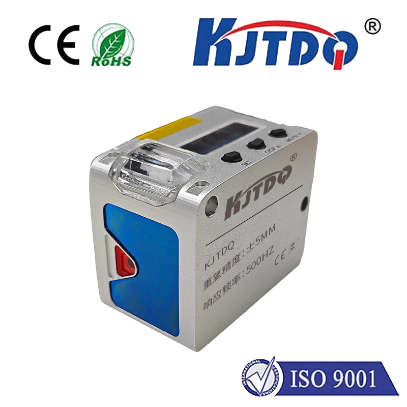
- Analog Output (Optional): Some advanced sensors provide a continuous analog voltage or current output (e.g., 0-10V, 4-20mA) proportional to the target distance, offering more granular information than simple on/off detection.
- Digital Protocols (Optional): Higher-end sensors might integrate interfaces like IO-Link, providing detailed sensor diagnostics, configuration options, and process data beyond simple state switching.
4. Housing, Lens, and Environmental Protection: The Essential Shield
These physical components are critical for real-world performance and longevity:
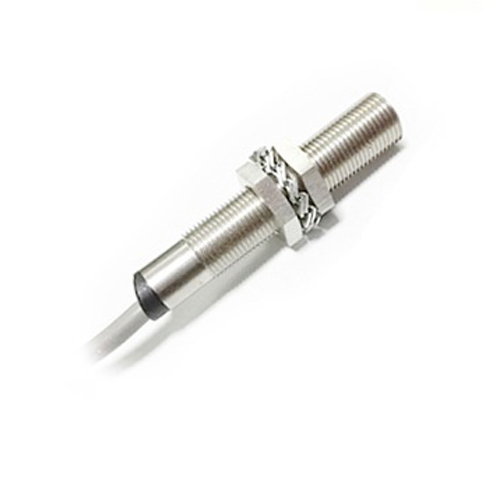
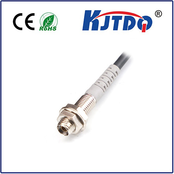
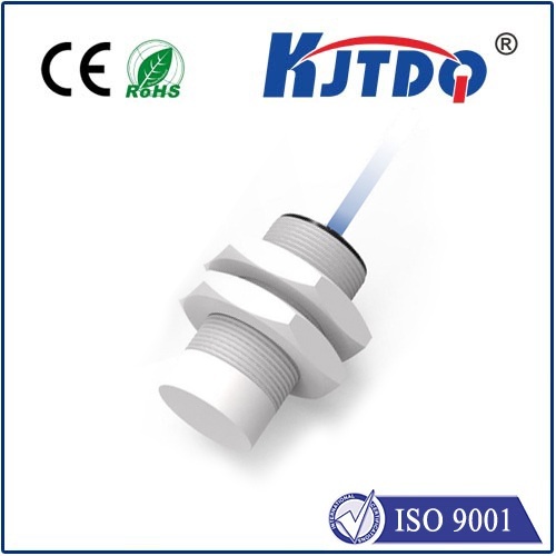
- Sensor Housing: Encases and protects all internal electronics. Constructed from robust materials like stainless steel (common for inductive sensors), nickel-plated brass, engineered plastics (PBT, PPS), or ceramic. Material choice affects durability, chemical resistance, and suitability for specific environments (e.g., food-grade, washdown).
- Sensing Face/Lens: The crucial interface point.
- Inductive Sensors: Often a non-ferrous metal cap or ferrite-loaded plastic protecting the coil. Material and thickness directly impact the sensing range.
- Capacitive Sensors: Typically feature an insulating dielectric material (plastic, ceramic) covering the electrodes, protecting them and defining the sensitivity field. Grounding/shielded designs often have a ring surrounding the sensing face.
- Photoelectric Sensors: Require an optical lens (plastic or glass) to collimate/focus the IR beam and protect the emitter/detector. Lens quality heavily influences range and resistance to environmental contamination.
- Cable or Connector: Provides power and signal connection. Shielded cable is often essential to prevent EMI/RFI disrupting the sensitive analog circuitry. Connectors (e.g., M8, M12) offer ease of installation and replacement.
- Environmental Sealing: Measured by an IP (Ingress Protection) rating (e.g., IP67, IP69K). This defines the sensor’s resistance to dust and liquids. Robust sealing via O-rings, potting compounds, and tight housing tolerances is vital for operation in harsh conditions like manufacturing floors or washdown areas.