check

check

check

check
check

check
check
check
check
check
That unexpected machine stop, the conveyor jamming mysteriously, the frustrating downtime – often, the culprit is surprisingly simple: a proximity sensor wired incorrectly. In the intricate dance of industrial automation, where machines communicate silently and precisely, proximity sensors are the unsung heroes, the silent sentinels detecting presence without touch. But when it comes to connecting them, a fundamental choice arises: NPN or PNP? Understanding this distinction isn’t just technical jargon; it’s the key to reliable machine operation and saving countless hours of troubleshooting headaches.
What Exactly Does a Proximity Sensor Do?
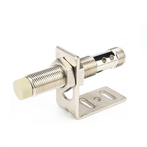
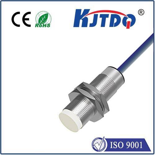
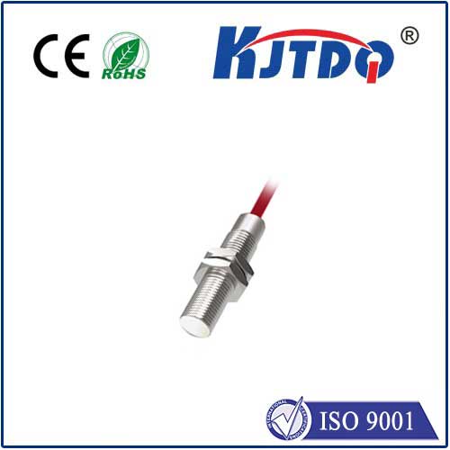
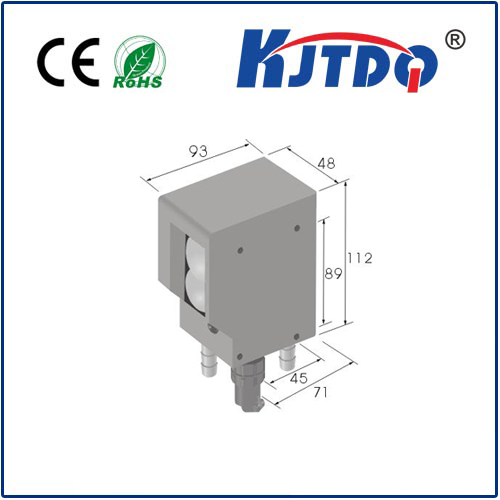
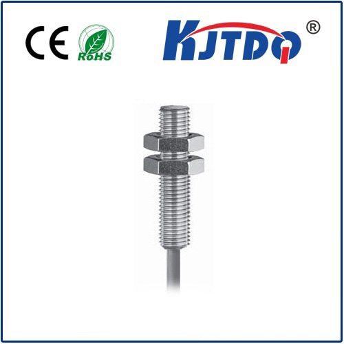
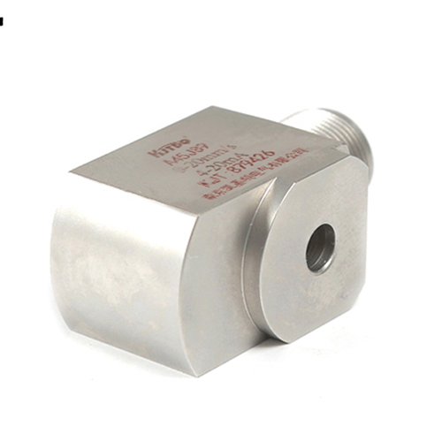
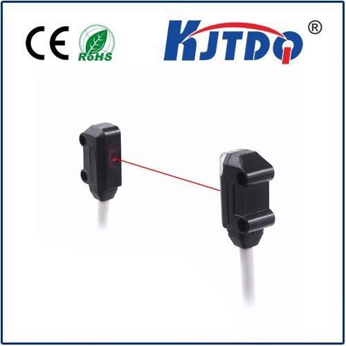
Before diving into NPN and PNP, let’s recap their primary function. Proximity sensors, operating on inductive (for metals), capacitive (for various materials), or photoelectric (light-based) principles, detect the presence or absence of an object within their sensing range without physical contact. They achieve this by emitting a field (electromagnetic or light) and monitoring disturbances caused by a target object entering that field. Their output is an electrical signal indicating “detected” or “not detected” – essentially acting as an electronic switch.
The Heart of the Matter: NPN and PNP Explained
The labels NPN proximity sensor and PNP proximity sensor refer to the type of transistor used inside the sensor to perform the switching action. This internal transistor type dictates how the sensor connects to the control system (like a PLC - Programmable Logic Controller) and the behavior of its output signal.
PNP Proximity Sensor (Positive Switching):
Operation: Think of PNP as sourcing current. When the sensor detects a target, its internal transistor switches ON, connecting the output signal line to the positive power supply voltage (usually labeled +V or +24V). This creates a positive voltage on the output line relative to the common (0V) or negative line.
Output Behavior: NO (Normally Open) Type: Output is OFF (0V) when no target is present. Output turns ON (+V) when target detected. NC (Normally Closed) Type: Output is ON (+V) when no target is present. Output turns OFF (0V) when target detected.
Wiring Symbol: Often indicated by a switch symbol pointing away from the positive supply within a circle on wiring diagrams. Remember: PNP = Positive ON.
NPN Proximity Sensor (Negative Switching):
Operation: Think of NPN as sinking current. When the sensor detects a target, its internal transistor switches ON, connecting the output signal line to the negative power supply voltage (usually 0V or GND). This pulls the output line down to 0V relative to the common.
Output Behavior: NO (Normally Open) Type: Output is OFF (“floating” or pulled high externally) when no target present. Output turns ON (0V) when target detected (sinks to ground). NC (Normally Closed) Type: Output is ON (sinks to ground) when no target present. Output turns OFF (“floating”) when target detected.
Wiring Symbol: Often indicated by a switch symbol pointing towards the negative supply within a circle on wiring diagrams. Remember: NPN = Negative ON (sinks to ground).
Sinking vs. Sourcing: The Practical Connection
The core difference manifests in how they interface with the input module of your PLC or controller:
Choosing Between NPN and PNP: What Matters Most?
Common Pitfalls and Troubleshooting Tips
Getting the Detection Right
There is no universally “better” choice between NPN proximity sensors and PNP proximity sensors. The right choice is dictated by the specific requirements of your control system, primarily the capabilities of your PLC input module. Understanding their core difference – whether they source positive current (PNP) or sink current to ground (NPN) – is fundamental to successful integration and troubleshooting. By selecting the correct type and wiring it accurately, you ensure these vital components perform their silent, non-contact detection role flawlessly, keeping your industrial processes running smoothly and efficiently