inductive proximity sensor fritzing
- time:2025-07-11 02:34:47
- Click:0
Mastering Inductive Proximity Sensor Simulation: Your Fritzing Guide to Non-Contact Detection
Ever wondered how factories detect metal parts whizzing by on conveyor belts without ever touching them? Or how heavy machinery knows not to close a safety gate if something’s in the way? The unsung hero is often the humble inductive proximity sensor. These rugged, reliable workhorses silently enable countless automation tasks. But how do you design circuits incorporating them before building physical prototypes? That’s where Fritzing, the beloved open-source electronics prototyping tool, steps in. Let’s dive into simulating and wiring inductive proximity sensors within Fritzing to bring your automated projects to life.
Understanding the Inductive Proximity Sensor: The Core Principle
At its heart, an inductive proximity sensor operates on the principles of electromagnetic induction. Essentially, it generates a high-frequency oscillating electromagnetic field from its sensing face. When a conductive target (like metal) enters this field, small circulating currents called eddy currents are induced within that target. The presence of these eddy currents dampens the sensor’s own oscillation field.

The sensor’s internal electronics constantly monitor the strength of this oscillation. The change in amplitude caused by the eddy currents triggers a switching action within the sensor. It doesn’t physically “feel” the target; it detects the disturbance its metal presence creates in the electromagnetic field. This makes them incredibly durable, immune to dirt, oil, and vibration issues that plague mechanical switches. Common applications include:
- Position detection (is the part in place?)
- End-of-travel sensing (has the cylinder fully extended?)
- Object counting (how many bottles passed?)
- Machine safety (is the guard closed?)
- Speed monitoring (detecting gear teeth)
Wiring the Workhorse: NPN vs. PNP and Connections
Before jumping into Fritzing, grasping real-world wiring is crucial. Inductive proximity sensors primarily come in two output transistor configurations: NPN (Sinking) and PNP (Sourcing). This distinction fundamentally impacts how you connect them to your controller (like an Arduino) and power supply.
- NPN (Sinking) Output:
- The output transistor acts like a switch to ground (0V).
- When active (target detected), the output pin connects internally to the negative (0V) supply line.
- Requires a “pull-up” resistor connected between the output pin and the positive supply voltage (e.g., +12V or +24V) to generate a usable voltage signal at the load (e.g., PLC input or Arduino pin).
- Commonly used with PLCs configured for sinking inputs.
- PNP (Sourcing) Output:
- The output transistor acts like a switch to the positive supply voltage.
- When active (target detected), the output pin connects internally to the positive supply line.
- Requires a connection to ground (0V) at the load to complete the circuit.
- Commonly used with PLCs configured for sourcing inputs or directly with microcontrollers like Arduino (though level shifting might be needed for 5V logic).
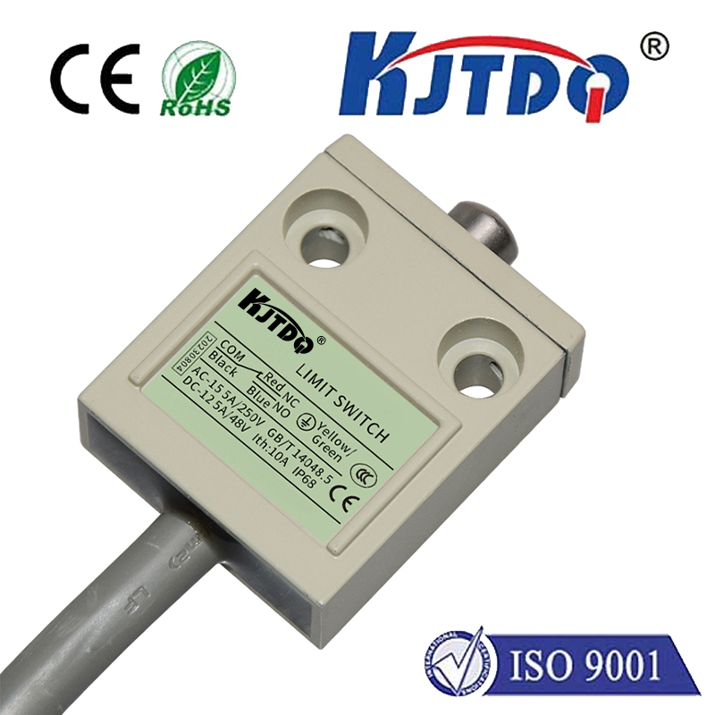
Crucially, both types require a 3-wire connection:
- Brown Wire (or Red): Connect to Positive Supply Voltage (Typically +10V to +30V DC).
- Blue Wire (or Black): Connect to Ground (0V).
- Black Wire (or output color like White/Yellow/Blue): This is the Switched Output Signal. Its behavior depends on whether it’s NPN or PNP.
Bringing it to Fritzing: Simulating Your Sensor Circuit
Fritzing shines as a user-friendly tool for designing and documenting breadboard, schematic, and PCB layouts. While its core parts library is extensive, you might not find the exact inductive proximity sensor model. Here’s the practical approach to simulate one effectively:
- Find a Suitable Stand-in Part:
- Use the Fritzing Search Box: Try keywords like “proximity,” “sensor,” or generic part numbers (e.g., searching for “LJ12A3” might yield a generic 3-wire sensor representation).
- Browse the “Output” or “Sensors” sections in the Parts Palette. Look for generic 3-wire sensor symbols – often depicted as a cylinder with a sensing face. The specific visual isn’t critical; the electrical behavior is.
- Consider Generic ICs/Transistors: If no sensor graphic suits you, drag a generic IC or transistor symbol onto the breadboard/Schematic view. Label it clearly (e.g., “Inductive Prox Sensor - PNP”). The key is representing the 3 connection points (V+, GND, OUT).
- Understand and Label the Connections:
- Identify the 3 pins on your chosen Fritzing part. Right-click -> Edit the part to see which pin is which internally. This is vital!
- Rename the pins clearly: Right-click on a pin -> Edit. Change the names to reflect standard proximity sensor wiring:
V+ or +Vs (Brown wire equivalent)GND or 0V (Blue wire equivalent)OUT or SIG (Output wire equivalent - Black/White)- Optionally, change the part image description to “Inductive Proximity Sensor” via the Inspector.
- Simulate the Wiring Correctly:
- Power: Connect the
V+ pin to your positive power rail (e.g., +12V source). Connect the GND pin to the ground (GND) rail.
- Output Handling (Critical):
- If simulating an PNP Sensor: Connect the
OUT pin directly or via an input indicator (like an LED/resistor combo) to your microcontroller’s Input Pin (e.g., Arduino D2). Remember, when active (detected), PNP OUT goes high (+V).
- If simulating an NPN Sensor: You must add a pull-up resistor (e.g., 10K Ohms) between the
OUT pin and the positive power rail (+V). Then connect the OUT pin to your microcontroller’s Input Pin. When active (detected), NPN OUT sinks current and goes low (0V). The pull-up ensures the input pin sees a high voltage when the sensor is inactive.
- Microcontroller Connection: Connect the chosen Arduino Input Pin to the circuit you built for the sensor output (either directly for PNP, or after the pull-up resistor for NPN). Use
digitalRead() in sketches to sense the state.
- Document with Clarity:
- Use Labels liberally! Label the sensor as PNP or NPN. Label your power rails. Label the Arduino pin used.
- Add Annotations (Breadboard or Schematic view -> Toolbar) to explain non-obvious choices, like “10K Pull-up Resistor Required for NPN Sensor”.
- Export views (Breadboard, Schematic, PCB) for your project documentation or instructions. Fritzing’s core strength here is clear visual documentation.
Key Considerations When Simulating & Using Inductive Proximity Sensors
- Sensor Range: Inductive sensors have a nominal sensing range (e.g., 2mm, 4mm, 8mm). Ensure your simulated detection distance makes sense physically.
- Target Material: Sensor range is specified for mild steel. Other metals (stainless steel, aluminum, copper) have reduction factors. Simulate accordingly (e.g., if sensing aluminum, represent it