inductive proximity sensor for rpm measurement - KJT
搜索

inductive proximity sensor for rpm measurement

  • time:2025-07-10 01:10:14
  • Click:0

Beyond the Tachometer: Mastering RPM Measurement with Inductive Proximity Sensors

Imagine monitoring the beating heart of your machinery – the rotational speed – without ever touching it, even in the harshest industrial environments. Dust swirls, grease coats surfaces, and vibration rattles components, yet a reliable signal pulses back, faithfully reporting every revolution. This isn’t magic; it’s the practical power of inductive proximity sensors applied to RPM measurement. For engineers and technicians seeking robust, non-contact speed monitoring, understanding this technique unlocks significant advantages in predictive maintenance and process control.

The Unseen Guardian: How Inductive Proximity Sensors Work

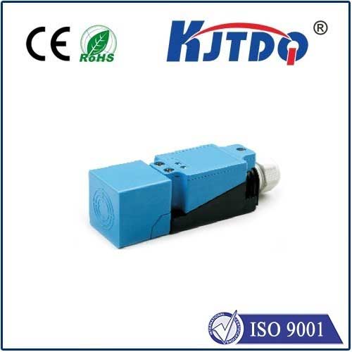
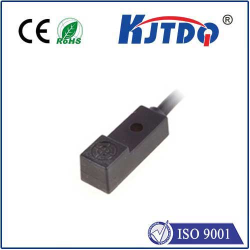
At its core, an inductive proximity sensor is an electronic device detecting the presence of metallic objects without physical contact. It operates on the principle of electromagnetic induction. Inside the sensor’s active face lies an oscillator circuit generating a high-frequency electromagnetic field. When a metallic target enters this field, eddy currents are induced within the target. These eddy currents absorb energy from the sensor’s oscillator, causing a detectable change in its amplitude. The sensor’s internal circuitry monitors this amplitude change and triggers a switching output (typically a clean, digital ON/OFF signal) when the target is sufficiently close. This non-contact detection is key to their reliability, eliminating wear and tear common with mechanical switches.

Transforming Pulses into Revolutions: The RPM Measurement Principle

So, how does detecting a piece of metal translate into measuring rotations per minute? The answer lies in carefully placing the sensor near a rotating metallic target feature on the shaft or attached component. Common targets include:

  1. Gear Teeth: The sensor is positioned facing the side of a gear. As each tooth passes the sensor, it triggers a detection pulse. The gap between teeth causes the pulse to drop.
  2. Keyways or Shaft Notches: A single notch or keyway milled into the shaft can be detected once per revolution.
  3. Encoder Discs: Purpose-made discs with alternating metallic/non-metallic segments or multiple teeth offer higher resolution.
  4. Bolt Heads or Other Features: Existing bolts on a rotating flange can serve as targets.

Each time a metallic target feature passes the inductive proximity sensor, it generates a distinct pulse. RPM measurement becomes a task of counting these pulses over a specific time interval or measuring the time between consecutive pulses.

  • Pulse Counting Method: Count the number of pulses (N) received over a fixed time period (T in seconds). If there is K target features per revolution (e.g., number of gear teeth, or 1 for a single notch), then: RPM = (N / (K * T)) * 60
  • Period Measurement Method: Measure the time (T_p in seconds) between two consecutive pulses (the pulse period). For K target features per revolution, the time for one full revolution (T_rev) is T_p * K. Thus: RPM = 60 / (T_p * K)

The sensor’s clean, fast-switching digital output signal is ideally suited for connection to programmable logic controllers (PLCs), digital counters, tachometers, or dedicated RPM monitoring devices that perform the necessary calculations.

Why Choose Inductive Proximity for RPM Duty? Key Advantages

The popularity of inductive proximity sensors for rotational speed sensing stems from compelling benefits:

  • Ruggedness & Reliability: Encased in robust materials (often stainless steel or nickel-plated brass), they withstand significant shock, vibration, and ingress protection (IP67/IP69K ratings are common). They laugh off dirt, dust, oil, and coolant splashes – environments where optical sensors might falter.
  • True Non-Contact Operation: No physical touch means zero mechanical wear on either the sensor or the target. This translates to exceptionally long service life and minimal maintenance.
  • High Switching Frequencies: Modern inductive sensors offer high response speeds, capable of detecting targets moving at high velocities and generating pulses for accurate RPM calculation even on fast-spinning machinery. Look for specifications in the hundreds of Hz to kHz range.
  • Simplicity and Cost-Effectiveness: They offer a straightforward, well-understood technology that is generally more affordable than optical encoders or laser tachometers, especially for standard industrial applications.
  • Versatility: The ability to use existing metallic features (gears, bolts, keyways) often eliminates the need for complex or costly retrofitting with special encoder wheels.

Implementation Best Practices for Accurate Readings

Maximizing the accuracy and reliability of your inductive RPM measurement setup requires attention to detail:

  1. Target Selection & Mounting: Choose a prominent, consistent metallic target. Ensure the sensor is mounted perpendicular to the target’s plane of movement at the correct sensing distance (specified as the sensor’s nominal range, Sn). Account for any target runout or wobble. Mounting stability is crucial to prevent signal fluctuation.
  2. Sensing Distance & Hysteresis: Operate within the sensor’s specified range. Understand its hysteresis (the difference between the switch-on and switch-off point), which provides noise immunity but must be considered for small target features. Generally, the target size should be at least equal to the sensor’s face diameter.
  3. Environment: While rugged, avoid placing sensors directly in strong magnetic fields, which can interfere with their internal oscillator. Verify the sensor’s temperature range suits the application. Ensure cables are routed away from high-voltage lines to prevent electrical noise.
  4. Pulse Processing: Connect the sensor output to a device capable of high-speed input counting or period measurement. PLCs often have dedicated high-speed counter (HSC) modules. Debounce filtering (either in hardware or software) might be necessary to clean up noisy signals, though high-quality inductive sensors typically generate very clean pulses.
  5. Calculating K (Targets per Revolution): This is critical! A miscount here directly causes RPM error. Double-check if you’re measuring the passage of gear teeth (K = number of teeth), a single notch (K=1), bolts on a flange (K = number of bolts), etc. If using a dedicated encoder disc, know its PPR (Pulses Per Revolution).
  6. Shielding & Cabling: Use shielded cable grounded at one end (usually the controller end) to minimize electromagnetic interference (EMI) on the signal line, especially in electrically noisy industrial settings.

Beyond Basic RPM: Leveraging the Signal for Insight

The pulse train from an inductive proximity sensor isn’t just for calculating an average shaft speed. It’s a rich data source:

  • Speed Variation Monitoring: Track RPM fluctuations that might indicate load changes, process instability, or impending mechanical issues like belt slippage.
  • Overspeed/Underspeed Detection: Set hard limits within the monitoring device (PLC, safety relay) to trigger alarms or shutdowns if speed exceeds safe operating parameters.
  • Phase Difference Measurement: Using multiple sensors on different shafts or positions, measure timing differences between events (e.g., camshaft/crankshaft timing).
  • Condition Monitoring: Analyzing subtle changes in the pulse timing pattern (period jitter) can sometimes provide early warnings about bearing wear or imbalance long before vibration becomes severe.

From the relentless hum of a conveyor drive motor to the critical spin of a turbine shaft, inductive proximity sensors offer an exceptionally robust, reliable, and cost-effective solution for non-contact RPM measurement. By mastering their principles of operation, selection, and implementation, you gain a powerful tool for optimizing machinery performance, preventing costly downtime, and ensuring the smooth, efficient pulse of your industrial operations. Their ability to thrive where other sensors fail makes them an indispensable component in the engineer’s toolkit for speed sensing challenges.
Recommended products